
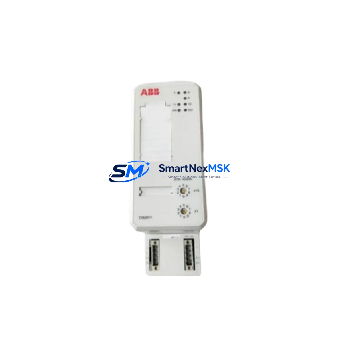
ABB CI820V1 3BSE025255R1 Maintenance-Ready Spare AC 800M Automation
The ABB CI820V1 (3BSE025255R1) is an original redundant PROFIBUS DP fieldbus interface module designed for the ABB AC 800M Distributed Control System platform. In industrial maintenance environments — from petrochemical plants and power generation facilities to pulp & paper mills and water treatment stations — the CI820V1 serves as a critical communication bridge between the AC 800M controller and field-level PROFIBUS DP devices including variable frequency drives, remote I/O stations, intelligent valve positioners, and process transmitters.
When a CI820V1 fails or degrades, the consequences extend far beyond a single I/O channel. An entire PROFIBUS segment — potentially dozens of field instruments — can go offline simultaneously, triggering process shutdowns, safety interlocks, and unplanned downtime. Sourcing a verified original replacement unit with a confirmed 12-month warranty is the fastest path to restoring full system operation. Every unit we supply is tested prior to shipment, documented with inspection records, and packaged to IEC transport standards to ensure it arrives ready for immediate installation.
Spare Maintenance Table
| Parameter | Specification |
|---|---|
| Part Number | CI820V1 |
| Reference Number | 3BSE025255R1 |
| Brand | ABB |
| Series / Platform | AC 800M DCS |
| Module Type | Redundant PROFIBUS DP Fieldbus Interface |
| Communication Protocol | PROFIBUS DP (IEC 61158) |
| Redundancy Support | Yes — Hot Standby redundancy capable |
| Backplane Interface | AC 800M S800 I/O Bus |
| Operating Voltage | 24 VDC (supplied via controller backplane) |
| Operating Temperature | 0°C to +55°C |
| Storage Temperature | -25°C to +70°C |
| Humidity | 5–95% RH, non-condensing |
| Protection Class | IP20 |
| Country of Origin | Germany |
| Compatibility | AC 800M PM851, PM856, PM860, PM861, PM864, PM866 controllers |
| Installation | DIN rail / controller rack slot, hot-swap capable in redundant configuration |
| Pre-shipment Testing | Yes — functional communication test performed |
| Warranty | 12 Months from date of shipment |
| Condition | Original, unused or refurbished-to-spec |
Maintenance Planning for Continuous Operation
Replacing the CI820V1 in an AC 800M control cabinet is rarely an isolated task. Experienced maintenance engineers treat a fieldbus interface replacement as an opportunity to audit the entire PROFIBUS segment and associated control infrastructure. Before returning the system to service, the following components should be inspected or tested alongside the CI820V1:
- PM856 / PM864 Controller Module — Verify the host controller firmware version is compatible with the CI820V1 hardware revision. A firmware mismatch can prevent the fieldbus interface from initializing correctly after replacement.
- TB820V2 ModuleBus Modem — If the CI820V1 is installed in a remote S800 I/O station, the TB820V2 optical ModuleBus modem must be checked for signal integrity and fiber connector cleanliness.
- S800 I/O Modules (AI810, AO810, DI810, DO810) — Inspect adjacent analog and digital I/O modules for loose backplane connectors, blown channel fuses, or LED fault indicators that may have been masked by the fieldbus communication fault.
- PROFIBUS DP Termination Resistors — Confirm that bus termination is active only at the two physical ends of the PROFIBUS segment. Incorrect termination is a leading cause of intermittent communication errors that mimic module failure.
- 24 VDC Power Supply (e.g., ABB CP-E 24/10.0) — Measure supply voltage at the controller rack under load. Voltage sag below 21.6 VDC can cause the CI820V1 to reset or fail to initialize the PROFIBUS master stack.
- PROFIBUS Cable and Connectors (9-pin Sub-D) — Inspect cable shielding continuity and connector pin seating. Damaged shielding on PROFIBUS cables introduces noise that degrades communication reliability, particularly in high-EMI environments near variable frequency drives.
- CI854A / CI856 Fieldbus Interface Modules — If the control system also uses FOUNDATION Fieldbus H1 or HART multiplexer interfaces in the same cabinet, verify their status indicators during the maintenance window, as a shared power rail fault can affect multiple interface modules simultaneously.
- Optical Fiber Patch Cords (for redundant ModuleBus) — In redundant AC 800M configurations, inspect both primary and secondary fiber paths for bend radius violations, dirty connectors, or physical damage that could compromise failover performance.
- Cabinet Cooling and Ventilation — Confirm that cabinet fans are operational and air filters are clean. Sustained operating temperatures above 50°C accelerate capacitor aging in fieldbus interface modules and reduce MTBF significantly.
- UPS / Battery Backup System — Test the uninterruptible power supply capacity and battery health. A weak UPS that cannot sustain the controller rack during a mains interruption can cause repeated uncontrolled shutdowns that damage flash memory in communication modules.
Documenting the pre-replacement PROFIBUS segment configuration — including GSD file versions, slave addresses, and baud rate settings — in a maintenance logbook reduces re-commissioning time and provides a baseline for future fault diagnosis.
Site Replacement Workflow
Step 1 — Compatibility Verification: Confirm the replacement CI820V1 (3BSE025255R1) hardware revision matches or is backward-compatible with the existing AC 800M controller firmware. Cross-reference the ABB AC 800M Hardware Configuration manual and the CI820V1 product changelog.
Step 2 — Backup System Configuration: Export the current Control Builder M project, including hardware configuration and PROFIBUS GSD assignments, before any physical intervention. Store the backup on an isolated engineering workstation.
Step 3 — Safe Module Removal: In a non-redundant configuration, coordinate with the process control team to place the affected PROFIBUS segment in manual or safe-state before removing the faulty CI820V1. In a redundant configuration, switch control to the standby path before hot-swapping the primary module.
Step 4 — Physical Installation: Seat the replacement CI820V1 firmly into the designated rack slot. Reconnect the PROFIBUS DP cable and verify connector locking. Do not power the module until all connections are secured.
Step 5 — Re-commissioning and Testing: Power up the module and observe the LED status indicators. A steady green RUN LED and absence of ERR/BUS fault LEDs confirm successful initialization. Use ABB Control Builder M to verify all PROFIBUS slave devices are communicating and process values are within expected ranges before releasing the segment to automatic control.
Step 6 — Documentation: Record the replacement date, module serial number, firmware version, and post-replacement test results in the plant maintenance management system (CMMS). Schedule the next preventive inspection interval based on the module’s rated MTBF and site environmental conditions.
Spare Parts Support FAQ
Q1: Is the CI820V1 (3BSE025255R1) still available as a new original part, or only as refurbished?
We supply both original new-old-stock (NOS) and professionally refurbished-to-specification units. All refurbished units undergo full functional testing on a live AC 800M test bench, including PROFIBUS master communication verification, before shipment. The condition is clearly stated on the order confirmation, and both carry the same 12-month warranty.
Q2: How do I verify compatibility with my specific AC 800M controller revision before ordering?
Provide your PM8xx controller model number and current firmware version (visible in Control Builder M under Hardware Configuration). We will cross-reference the ABB compatibility matrix and confirm the correct CI820V1 hardware revision for your system before the order is processed. This eliminates the risk of a firmware-hardware mismatch on site.
Q3: What is the typical lead time, and can you support emergency same-day dispatch?
Standard orders ship within 1–3 business days after payment confirmation. For critical plant shutdowns, we offer priority processing with same-day or next-day dispatch subject to stock availability. Contact our sales team directly at [email protected] or +86 18259474341 to confirm emergency availability before placing the order.
Q4: What does the 12-month warranty cover, and what is the claims process?
The 12-month warranty covers manufacturing defects, functional failures under normal operating conditions, and any fault attributable to the module itself rather than external wiring or power supply issues. To initiate a warranty claim, contact us with the order number, a description of the fault symptom, and photos of the LED status indicators and installation environment. We will arrange return shipping and provide a replacement or full refund within the agreed resolution timeframe.
© 2026 SMARTNEXMSK. All rights reserved.
Original Source: https://smartnexmsk.com
Contact: [email protected] | +86 18259474341



