
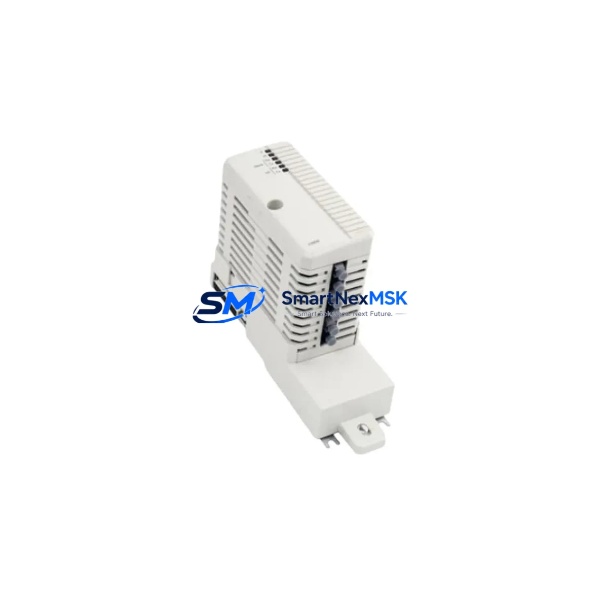
ABB CI858K01 Retrofit-Ready DriveBus Interface for AC 800M Control Systems
The ABB CI858K01 is a DriveBus Communication Interface Module engineered for seamless integration within the AC 800M distributed control architecture. As legacy automation lines age and OEM support windows close, the CI858K01 has become one of the most sought-after retrofit components for engineers tasked with modernizing S800 I/O-based control cabinets without full system replacement. Whether you are replacing a failed unit on a running production line, upgrading a discontinued communication link, or migrating from an older AC 800 platform, the CI858K01 delivers the compatibility and reliability that industrial retrofit projects demand.
This module mounts directly onto the S800 I/O station and establishes a DriveBus link between the AC 800M controller and connected ABB drives — including ACS800, ACS600, and DCS800 series — enabling coordinated speed and torque control across multi-drive applications. Its compact form factor and standard S800 rail mounting make it a drop-in candidate for most existing control cabinet layouts, significantly reducing mechanical rework during upgrade projects.
Upgrade Compatibility Table
| Parameter | Details |
|---|---|
| SKU / Part Number | CI858K01 |
| Brand / Series | ABB / AC 800M, S800 I/O |
| Module Function | DriveBus Communication Interface |
| Compatible Controllers | AC 800M (PM861, PM864, PM866) |
| Compatible Drives | ACS800, ACS600, DCS800 |
| Mounting Interface | S800 I/O Rail (standard backplane) |
| Communication Protocol | DriveBus (ABB proprietary fieldbus) |
| Power Supply | Supplied via S800 I/O backplane (no external PSU required) |
| Replaces / Supersedes | CI858, CI858A (earlier hardware revisions) |
| Installation Requirement | Module address set via hardware DIP switch; confirm node address before power-on |
| Commissioning Note | Verify DriveBus node address in Control Builder M; re-download application if address changed |
| Warranty | 12 Months — covers manufacturing defects and functional failure under normal operating conditions |
Retrofit Planning for Existing Automation Systems
Successful CI858K01 retrofit projects begin well before the module arrives on site. Engineers should start by auditing the existing S800 I/O station layout, confirming available backplane slots and verifying that the TB820 ModuleBus Modem or TB840 Optical ModuleBus Modem currently in use is compatible with the target firmware revision of the replacement CI858K01. In multi-drop DriveBus topologies, each CI858K01 node must carry a unique address — duplicate addressing is one of the most common commissioning errors encountered during drive communication upgrades.
Power budget verification is equally critical. The S800 I/O backplane distributes 24 VDC across all installed modules; adding or replacing a CI858K01 requires confirming that the existing PS800 power supply or SD821/SD822 power supply unit has sufficient headroom. In cabinets where multiple SA811 or SA801 analog I/O modules are already loaded, available current margin may be tighter than expected.
Terminal wiring for the DriveBus cable — typically a shielded twisted-pair routed from the CI858K01 to the drive’s RDBU-xx DriveBus adapter board — should be inspected for insulation integrity and correct shield grounding at the drive end only. Improper shield termination is a frequent source of intermittent communication faults that are difficult to diagnose after commissioning.
On the software side, the Control Builder M project must reflect the new module’s hardware revision. If the replacement CI858K01 carries a different hardware suffix than the original, the I/O configuration in the AC 800M application may require a hardware update step before the program can be downloaded. Backup the existing application — including all POU logic, variable lists, and communication configurations — before initiating any hardware change. Where the control system also interfaces with an ABB Freelance 800F or Symphony Plus DCS layer via OPC or PROFIBUS DP, confirm that the drive status signals mapped through the CI858K01 are correctly re-established after the module swap.
HMI screens connected via an ABB Panel 800 operator terminal or a third-party SCADA system should be validated post-commissioning to ensure that drive speed references, fault codes, and run/stop status signals are updating correctly. In plants where the CI858K01 feeds data into a historian or MES layer, a brief functional test of the data pipeline before returning the line to production is strongly recommended.
Downtime Control During System Migration
Minimizing unplanned downtime is the primary concern for any CI858K01 replacement on a live production system. The recommended approach is to pre-configure and bench-test the replacement module before the scheduled maintenance window. Set the DriveBus node address on the new CI858K01 to match the outgoing unit, verify the module powers up correctly on a spare S800 backplane or test rack, and confirm that Control Builder M recognizes the module without hardware mismatch warnings.
During the swap window, document the existing DriveBus cable routing and terminal connections before disconnection. Label each cable clearly — particularly in multi-drive cabinets where several CI858K01 modules may be installed in adjacent slots. Power down the S800 I/O station in the correct sequence: disable the AC 800M application, then remove power from the backplane before extracting the module. Hot-swap capability is not supported on the CI858K01; attempting live removal risks corrupting the ModuleBus communication state and may trigger a controller fault that affects other I/O stations on the same rack.
After installing the replacement CI858K01, restore power, allow the module to initialize, and confirm green LED status before re-downloading the Control Builder M application. Perform a controlled drive start at reduced speed reference to verify DriveBus communication integrity before returning the axis to full production speed. Keeping a pre-tested spare CI858K01 in local inventory — alongside a compatible RDBU-02 or RDBU-04 DriveBus adapter — is the most effective strategy for reducing mean time to repair on future incidents.
Retrofit Support FAQ
Q: Is the CI858K01 a direct drop-in replacement for the earlier CI858 and CI858A modules?
A: In most installations, yes. The CI858K01 is the current hardware revision and is backward compatible with the same S800 backplane slot and DriveBus wiring used by CI858 and CI858A. However, if your Control Builder M project was built against an older hardware revision, you may need to perform a hardware update in the I/O configuration before downloading the application. Always compare hardware revision strings in the module catalog before finalizing the replacement order.
Q: What commissioning steps are required after installing a CI858K01 in an existing AC 800M system?
A: Set the DriveBus node address via the DIP switch on the module face to match the address configured in the Control Builder M hardware tree. Power up the S800 station, confirm the CI858K01 LED status, then connect to the AC 800M controller and verify that the module appears online in the hardware status view. Re-download the application if prompted, then perform a supervised drive start to validate communication. Check all mapped drive signals — speed feedback, current, fault word — against expected values before releasing the system.
Q: Can the CI858K01 be used with ACS880 or ACS580 drives, or only with ACS800 and ACS600 series?
A: The CI858K01 uses ABB’s DriveBus protocol, which is natively supported by ACS800, ACS600, and DCS800 drives equipped with the appropriate RDBU DriveBus adapter. ACS880 and ACS580 drives use PROFIBUS DP, EtherNet/IP, or PROFINET as their primary fieldbus interfaces and do not support DriveBus natively. For AC 800M integration with ACS880 drives, the CI854 PROFIBUS DP Interface Module is the appropriate communication module.
Q: What does the 12-month warranty cover, and what is the process for a warranty claim?
A: The 12-month warranty covers manufacturing defects and functional failures under normal operating and storage conditions. It does not cover damage resulting from incorrect installation, overvoltage, reverse polarity, or physical impact. To initiate a warranty claim, contact our sales team with the order reference, a description of the fault symptom, and — where possible — the LED status observed at the time of failure. We will arrange return shipping and either repair or replace the unit within the agreed lead time.
© 2026 SMARTNEXMSK. All rights reserved.
Original Source: https://smartnexmsk.com
Contact: [email protected] | +86 18259474341



