
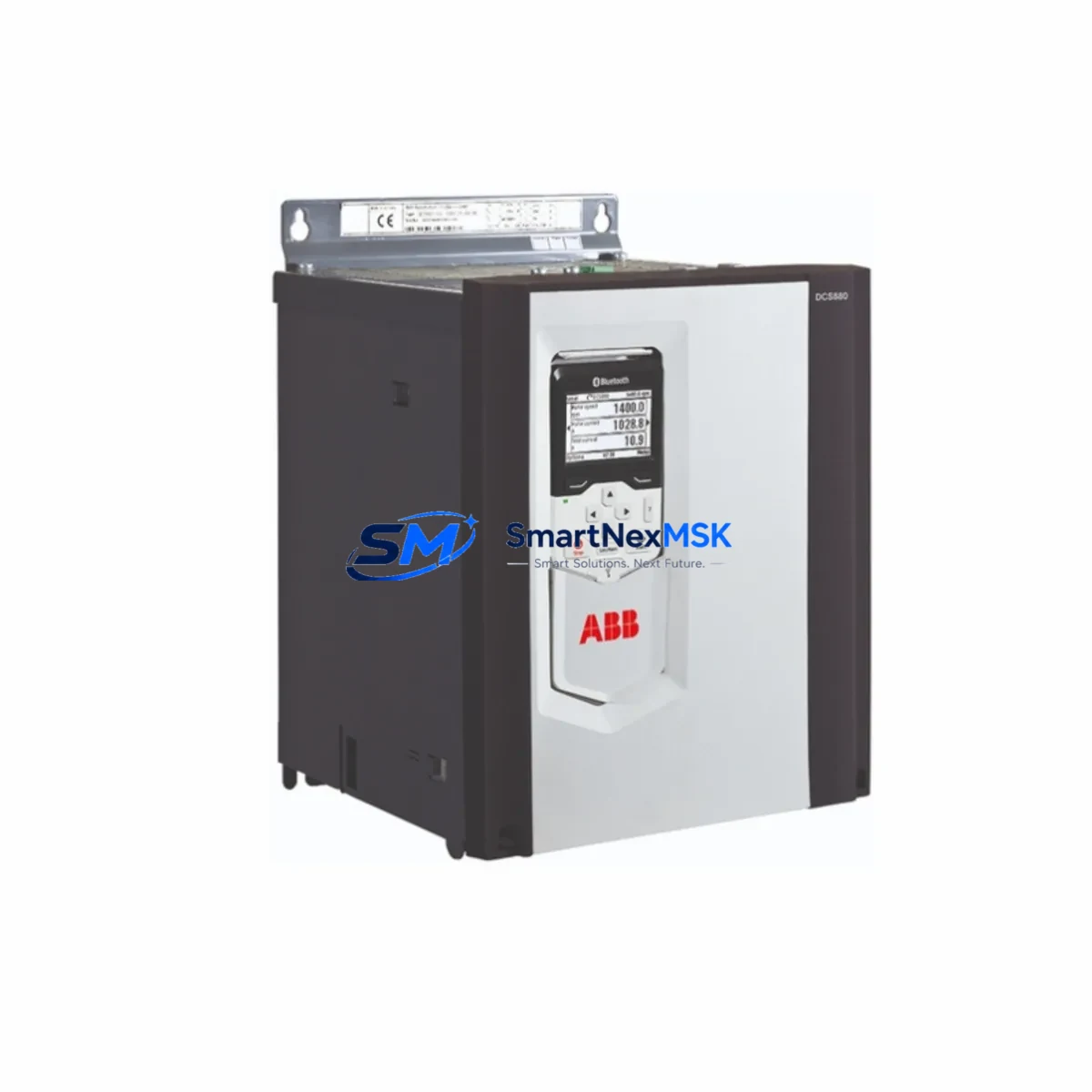
ABB DCF803-0050 Maintenance-Ready Spare for DCS800 Automation
The ABB DCF803-0050 Field Exciter Module is a critical spare part for ABB DCS800 Series DC drive systems deployed across heavy industrial environments including steel mills, paper machines, mining conveyors, and marine propulsion systems. When this module fails or degrades, the entire DC drive axis loses field excitation control, resulting in uncontrolled motor behavior and immediate production shutdown. Maintaining a verified replacement unit of the DCF803-0050 in your spare parts inventory is one of the most effective strategies for minimizing unplanned downtime and protecting long-term system availability.
At SMARTNEXMSK, every DCF803-0050 unit is sourced from authorized supply channels, individually inspected, and tested prior to shipment. Each unit ships with a 12-month warranty covering manufacturing defects and functional performance, giving maintenance engineers and procurement teams confidence in both quality and long-term supply continuity.
Spare Maintenance Table
| Parameter | Specification |
|---|---|
| SKU / Part Number | DCF803-0050 |
| Brand | ABB |
| Compatible Series | DCS800 DC Drive Series |
| Module Type | Field Exciter Module |
| Rated Output Current | 50 A (field excitation) |
| Supply Voltage | 230 / 400 / 480 V AC (configurable) |
| Control Interface | SDCS-CON-4 / SDCS-CON-F control board compatible |
| Mounting | DIN rail / drive cabinet integrated |
| Operating Temperature | 0°C to +55°C |
| Protection Class | IP00 (cabinet-mounted) |
| Origin | Germany |
| Application Environment | Heavy industry, steel, paper, mining, marine |
| Maintenance Recommendation | Inspect annually; replace at first sign of field current instability |
| Warranty | 12 Months |
| Availability | In Stock — Ready to Ship |
Maintenance Planning for Continuous Operation
When a DCF803-0050 Field Exciter Module is flagged for replacement during a planned shutdown or emergency callout, experienced maintenance engineers know that the field exciter rarely fails in isolation. A thorough inspection of the surrounding electrical circuit is essential to prevent repeat failures and ensure the drive returns to stable operation.
Begin by verifying the integrity of the SDCS-CON-4 control board or its successor SDCS-CON-F, which governs the firing signals sent to the DCF803-0050. A degraded control board can cause erratic field current output that mimics a faulty exciter module. Simultaneously, check the SDCS-POW-4 power supply board for voltage ripple or thermal stress — an unstable auxiliary power supply is a common root cause of field exciter faults in aging DCS800 cabinets.
Inspect all field winding connection terminals and associated terminal blocks for oxidation, loose crimps, or thermal discoloration. High-resistance connections in the field circuit can cause the DCF803-0050 to operate outside its rated parameters, accelerating wear. If the drive cabinet includes a SDCS-AMC-DC3 application module or a DDCS fiber optic communication adapter, verify that firmware versions are compatible with the replacement module to avoid parameter mismatch after commissioning.
For drives integrated into a broader automation network, check the RPBA-01 PROFIBUS adapter or RDNA-01 DeviceNet adapter for communication faults that may have been masked by the drive fault condition. It is also advisable to inspect the motor thermistor input circuit and any associated signal isolators to confirm that thermal protection signals are reaching the drive controller correctly. Finally, review the AC input fuses and DC bus fuse ratings — a field exciter fault can sometimes be preceded by transient overcurrent events that stress upstream protection components.
Procurement engineers should consider stocking the DCF803-0050 alongside the SDCS-CON-4 control board and SDCS-POW-4 power supply as a coordinated spare set. This approach significantly reduces mean time to repair (MTTR) for DCS800 drive cabinets and is consistent with best practices for critical drive asset management in continuous process industries.
Site Replacement Workflow
Step 1 — Isolation and Safety: Isolate the DCS800 drive from the AC supply and confirm zero voltage on the DC bus using a calibrated meter. Allow the DC bus capacitors to fully discharge before opening the cabinet.
Step 2 — Documentation: Photograph the existing DCF803-0050 wiring, terminal assignments, and DIP switch or parameter settings before removal. Record the drive’s parameter set using the DCS800 control panel (ACS-CP-D) or DriveWindow software if available.
Step 3 — Module Removal: Disconnect field output terminals (F+ / F−) and AC supply connections. Remove the module from its mounting position, noting any mechanical alignment features specific to the DCS800 cabinet frame.
Step 4 — Replacement Installation: Install the new DCF803-0050, reconnect all terminals to the documented configuration, and verify torque on all power connections. Confirm DIP switch settings match the original field voltage and current requirements.
Step 5 — Commissioning and Verification: Power up the drive in field-only mode and measure field current output against the motor nameplate field current specification. Use the drive’s diagnostic display or DriveWindow to confirm that field current feedback is stable and within tolerance before enabling armature control.
Step 6 — System Handover: Log the replacement in the maintenance management system, update the spare parts inventory, and confirm the next scheduled inspection interval for the field exciter circuit.
This workflow is applicable to both like-for-like replacement of a failed DCF803-0050 and proactive replacement during planned maintenance windows. The procedure supports system compatibility with all DCS800 variants including DCS800-S01, DCS800-S02, and DCS800-EP configurations.
Spare Parts Support FAQ
Q1: Is the DCF803-0050 compatible with all DCS800 drive ratings?
The DCF803-0050 is designed for DCS800 Series DC drives requiring a 50 A field excitation output. Compatibility depends on the specific drive rating and field winding requirements of the connected motor. Always verify the motor nameplate field current and cross-reference with the DCS800 hardware manual before installation. Our technical team can assist with compatibility confirmation prior to order.
Q2: How is each unit tested before shipment?
Every DCF803-0050 unit supplied by SMARTNEXMSK undergoes functional verification including output current measurement, insulation resistance check, and visual inspection for component integrity. Units are packed in anti-static, shock-protected packaging to ensure they arrive in field-ready condition.
Q3: What does the 12-month warranty cover?
The 12-month warranty covers manufacturing defects and functional failures under normal operating conditions. It does not cover damage resulting from incorrect installation, overvoltage events, or operation outside the module’s rated parameters. Warranty claims are supported with replacement or repair at no additional cost within the warranty period.
Q4: Can you support long-term or repeat procurement for DCS800 spare parts?
Yes. SMARTNEXMSK maintains ongoing inventory of DCS800 series components including field exciter modules, control boards, power supply boards, and communication adapters. We support blanket order arrangements and can provide lead time commitments for planned maintenance programs. Contact our team to discuss volume pricing and scheduled delivery options.
© 2026 SMARTNEXMSK. All rights reserved.
Original Source: https://smartnexmsk.com
Contact: [email protected] | +86 18259474341



