
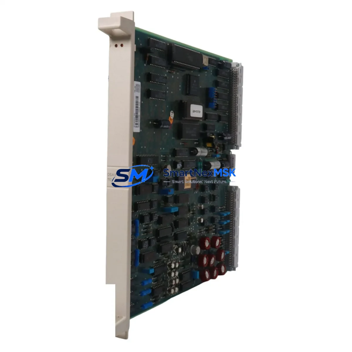
ABB DSAX110 57120001-PC Retrofit-Ready Analog I/O for INFI 90 Control Systems
The ABB DSAX110 57120001-PC is a proven analog input/output module engineered for the INFI 90 Distributed Control System platform. As legacy INFI 90 installations continue to operate across power generation, pulp and paper, chemical processing, and water treatment facilities worldwide, the demand for verified retrofit-ready replacements has never been higher. Whether you are managing a planned control cabinet upgrade, responding to an unplanned module failure, or executing a phased migration away from discontinued hardware, the DSAX110 57120001-PC delivers the electrical compatibility, backplane interface integrity, and signal accuracy required to restore and sustain production continuity.
This module supports both analog input and analog output channels, making it a versatile component in mixed-signal control loops. It is designed to seat directly into the INFI 90 rack system, maintaining the same physical footprint and backplane connector pinout as the original factory-installed unit. Engineers undertaking a retrofit should verify the power supply rail capacity within the existing control cabinet — the DSAX110 draws from the 24 VDC bus shared with other I/O modules such as the DSDX110 digital I/O module and the DSAI130 analog input module. Confirming that the existing ABB DSPU110 or DSMB115 power supply unit can sustain the additional load is a critical pre-installation step.
Terminal wiring on the DSAX110 57120001-PC follows the standard INFI 90 field termination convention. Field cables connected to the original module can typically be re-terminated without modification, provided that the termination unit — commonly the DSTC110 or DSTC454 terminal board — is in serviceable condition. Technicians should document the existing channel-to-terminal mapping before removal and cross-reference against the updated I/O list to prevent signal inversion or address conflicts during commissioning.
Module addressing within the INFI 90 architecture is managed through the Module Configuration Record (MCR) stored in the IMMFP12 or IMMFP02 multi-function processor. When installing a replacement DSAX110, the module address DIP switches must be set to match the original configuration. Failure to replicate the address settings will result in the controller failing to recognize the module on the INFI-NET or INFI-NET/ET communication loop, triggering a hardware fault alarm on the operator station. If the site uses an ABB Conductor NT or Conductor VMS SCADA/HMI platform, the associated display faceplates and alarm pages will reflect the module status in real time once the address is correctly configured.
For sites executing a broader migration from INFI 90 to the ABB System 800xA platform, the DSAX110 57120001-PC can serve as a bridge component during the transition period. It allows individual control loops to remain operational on the legacy backplane while adjacent loops are migrated to the S800 I/O family — including modules such as the AI810 analog input module or the AO810V2 analog output module — connected via the S800 Remote I/O bus. This phased approach minimizes the risk of simultaneous process disruption across multiple control loops and allows the engineering team to validate each migrated loop independently before decommissioning the legacy hardware.
Communication link integrity is another key consideration during retrofit planning. The INFI 90 system relies on the INFI-NET coaxial communication bus or the INFI-NET/ET Ethernet bridge for inter-module and controller-to-HMI data exchange. Before replacing the DSAX110, verify that the NDSC110 or NKTU01 communication interface modules on the same rack segment are functioning correctly. A degraded communication link can mask module faults and complicate post-installation diagnostics. All replacement modules supplied by SMARTNEXMSK are bench-tested for communication handshake compliance prior to shipment.
Every DSAX110 57120001-PC unit shipped by SMARTNEXMSK is covered by a 12-month warranty against manufacturing defects and functional failure under normal operating conditions. Units are sourced from verified supply channels, inspected for physical integrity, and tested for analog signal accuracy across the full channel range before dispatch. Inventory is maintained to support both emergency single-unit orders and planned bulk procurement for scheduled maintenance shutdowns.
Upgrade Compatibility Table
| Parameter | Detail |
|---|---|
| Compatible Platform | ABB INFI 90 DCS |
| Module Type | Analog Input / Output (Mixed) |
| Backplane Interface | INFI 90 Standard Rack Connector — direct drop-in |
| Power Requirement | 24 VDC via rack backplane (verify DSPU110 / DSMB115 capacity) |
| Terminal Compatibility | Compatible with DSTC110 / DSTC454 termination boards |
| Communication | INFI-NET / INFI-NET/ET (coaxial or Ethernet bridge) |
| Address Configuration | DIP switch — must match original MCR settings |
| HMI Compatibility | ABB Conductor NT, Conductor VMS, System 800xA (bridge mode) |
| Replacement Recommendation | Direct replacement for DSAX110 57120001-PC; verify firmware revision if applicable |
| Commissioning Focus | Channel mapping, address verification, signal loop calibration |
| Warranty | 12 Months — covers functional failure under normal operating conditions |
Retrofit Planning for Existing Automation Systems
A successful DSAX110 retrofit begins well before the module is physically removed from the rack. The engineering team should compile a complete inventory of the affected control cabinet, including the rack chassis model, the number of occupied slots, the installed DSPU110 power supply load, and the firmware versions of the IMMFP12 multi-function processor cards governing the affected I/O bus segment. This documentation forms the baseline for the retrofit plan and supports post-installation verification.
In cabinets where the DSAX110 shares a rack with DSDX110 digital I/O modules, DSDI110 discrete input modules, or DSDO110 discrete output modules, the technician must account for the cumulative backplane current draw. Overloading the power bus is a common cause of intermittent module faults in aging INFI 90 installations. If the power budget is marginal, replacing the DSMB115 power supply module or adding a supplementary power feed to the rack should be included in the retrofit scope.
Field wiring connected to the DSTC110 or DSTC454 termination board should be photographed and labeled before disconnection. Each analog channel — whether a 4–20 mA current loop, a 0–10 V voltage signal, or a thermocouple input — must be individually verified against the loop drawing. After the replacement DSAX110 57120001-PC is installed and addressed, a full channel-by-channel signal injection test using a calibrated loop calibrator is recommended before returning the loop to automatic control mode.
For sites that use the ABB NKTU01 or NDSC110 as the INFI-NET communication interface, the module replacement window should be coordinated with the control room operator to place the affected loops in manual mode via the Conductor NT or Conductor VMS operator station. This prevents spurious control outputs during the module swap and protects downstream field devices — including control valves, variable frequency drives, and motor starters — from unintended actuation.
If the retrofit is part of a larger migration to ABB System 800xA, the DSAX110 replacement can be executed in parallel with the installation of the AC800M controller and the S800 I/O bus infrastructure. The DSAX110 continues to serve the legacy loops while the new S800 I/O — including AI810 and AO810V2 modules — is commissioned on the new controller. Once the new loops are validated, the INFI 90 rack can be decommissioned in a controlled sequence, loop by loop, without a full plant shutdown.
Downtime Control During System Migration
Minimizing unplanned downtime is the primary operational constraint in any INFI 90 retrofit project. The DSAX110 57120001-PC is designed to support a hot-swap replacement strategy within the INFI 90 rack architecture, subject to the site’s safety procedures and the process criticality of the affected loops. Before initiating the swap, all loops served by the module should be placed in manual mode at the operator station. The IMMFP12 processor will log the module removal event, and the Conductor NT alarm system will generate a hardware fault notification — this is expected behavior and should be communicated to the control room in advance.
The original program logic stored in the IMMFP12 or IMMFP02 processor is not affected by the module replacement. The Module Configuration Record (MCR) retains the loop configuration, scaling parameters, alarm limits, and control algorithm assignments. Once the replacement DSAX110 is installed with the correct address settings, the processor will automatically re-establish communication with the module and reload the configuration. In most cases, the loops can be returned to automatic mode within minutes of installation, provided that the field signals are within the expected range and no wiring faults are detected during the post-installation check.
For critical loops where even brief manual operation is unacceptable, a pre-staged replacement strategy is recommended. The replacement DSAX110 57120001-PC should be bench-configured and address-verified before the maintenance window begins. SMARTNEXMSK supports pre-shipment configuration verification on request, reducing the on-site commissioning time to the minimum required for physical installation and signal loop confirmation. All units are shipped with a test report documenting the analog channel performance across the full signal range.
Retrofit Support FAQ
Q1: Is the DSAX110 57120001-PC a direct drop-in replacement for the original module?
Yes. The DSAX110 57120001-PC maintains the same backplane connector, physical dimensions, and channel configuration as the original factory-installed unit. No rack modification or wiring change is required, provided the termination board (DSTC110 or DSTC454) is in serviceable condition. The DIP switch address settings must be replicated from the original module before installation.
Q2: Will the replacement module affect the existing program logic or HMI displays?
No. The control program and loop configuration are stored in the IMMFP12 or IMMFP02 multi-function processor, not in the I/O module itself. The Conductor NT or Conductor VMS HMI displays will resume normal operation once the replacement module is recognized on the INFI-NET bus. No program download or HMI reconfiguration is required.
Q3: What commissioning steps are required after installation?
After physical installation and address verification, perform a channel-by-channel signal injection test to confirm analog accuracy across the full range. Verify that the IMMFP12 processor has re-established communication with the module (no hardware fault alarms active). Return each loop to automatic mode individually, monitoring the process variable for stability before proceeding to the next loop. Document the commissioning results for the site maintenance record.
Q4: What does the 12-month warranty cover?
The 12-month warranty covers functional failure of the DSAX110 57120001-PC under normal operating conditions, including analog channel accuracy degradation, backplane communication failure, and power supply interface faults. Physical damage caused by incorrect installation, overvoltage, or environmental exposure outside the module’s rated operating range is excluded. Warranty claims are supported by SMARTNEXMSK with replacement unit dispatch and return logistics coordination.
© 2026 SMARTNEXMSK. All rights reserved.
Original Source: https://smartnexmsk.com
Contact: [email protected] | +86 18259474341



