
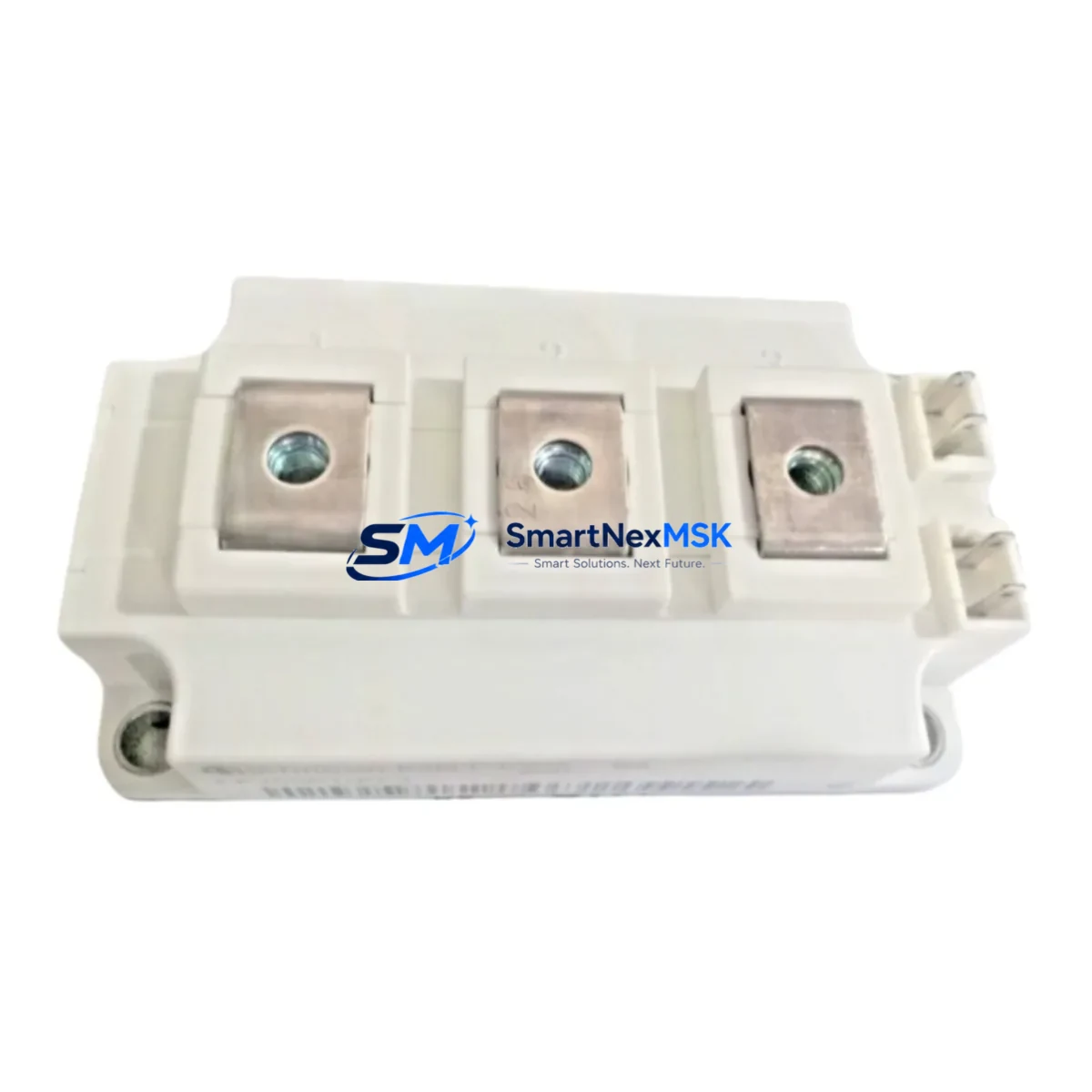
ABB FF300R12KE3 Maintenance-Ready Spare EconoPACK 3
Unplanned downtime in drive systems and industrial inverters is one of the most costly events in any manufacturing or process facility. The ABB FF300R12KE3 is a 300 A / 1200 V dual IGBT half-bridge power module in the EconoPACK 3 footprint — a critical switching component found in medium-power variable frequency drives (VFDs), regenerative converters, UPS systems, and traction inverters. Holding a verified original spare on the shelf is the single most effective strategy for reducing mean time to repair (MTTR) when a power stage fault is diagnosed.
This listing supplies the FF300R12KE3 as a maintenance-ready, tested spare. Each unit undergoes pre-shipment electrical verification covering gate threshold voltage, collector-emitter saturation voltage (VCE(sat)), and reverse recovery characteristics before dispatch. The module ships in anti-static packaging with full traceability documentation, backed by a 12-month warranty against manufacturing defects.
Spare Maintenance Table
| Parameter | Specification |
|---|---|
| Part Number / SKU | FF300R12KE3 |
| Brand | ABB (Infineon EconoPACK 3 platform) |
| Series | EconoPACK 3 |
| Module Type | Dual IGBT Half-Bridge |
| Collector Current (IC) | 300 A (TC = 80 °C) |
| Blocking Voltage (VCES) | 1200 V |
| VCE(sat) (typ.) | 2.0 V @ 300 A, 25 °C |
| Gate Drive Voltage | +15 V / −8 V (recommended) |
| Thermal Resistance (Rth(j-c)) | ≤ 0.10 K/W per switch |
| Package / Footprint | EconoPACK 3 (62 mm module) |
| Mounting Torque | 3 N·m (baseplate to heatsink) |
| Operating Temperature | −40 °C to +150 °C (Tj) |
| Application Environment | VFDs, regenerative converters, UPS, traction inverters |
| Compatibility | Drop-in replacement for FF300R12KE3 in ABB ACS, ACS800, ACS880 drive power stages and equivalent OEM designs |
| Origin | Germany |
| Pre-Shipment Test | VGE(th), VCE(sat), leakage, diode forward voltage |
| Warranty | 12 Months from date of shipment |
| Lead Time | In-stock; ships within 1–3 business days |
Maintenance Planning for Continuous Operation
When a power module fault is confirmed in a drive cabinet, experienced maintenance engineers know that replacing only the failed IGBT module is rarely sufficient for a durable repair. A thorough cabinet inspection should accompany every FF300R12KE3 replacement to prevent repeat failures and ensure the repaired drive returns to full rated performance.
Gate driver board: The gate driver PCB that interfaces directly with the FF300R12KE3 should be inspected for burnt gate resistors, damaged optocouplers, and degraded bootstrap capacitors. A faulty gate driver is frequently the root cause of IGBT desaturation events. If the driver board shows any signs of thermal stress, replace it alongside the module.
DC bus capacitor bank: Electrolytic DC link capacitors age with thermal cycling. Measure capacitance and ESR on all DC bus capacitors in the same power stage. Capacitors operating below 80% of rated capacitance or with elevated ESR should be scheduled for replacement. Capacitor failure causes voltage spikes that can destroy a newly installed FF300R12KE3 within hours of commissioning.
Current sensors and Hall-effect transducers: Phase current feedback is essential for overcurrent protection. Verify that all current sensors in the output phases are reading accurately. A drifted sensor can cause the drive controller to permit overcurrent conditions that stress the new module.
Snubber and clamp circuits: Inspect snubber capacitors and clamp diodes across the DC bus. These components absorb switching transients; degraded snubbers increase peak voltage stress on the IGBT during turn-off.
Thermal interface and heatsink: Remove old thermal compound from the heatsink mounting surface and apply fresh, high-conductivity thermal paste before installing the FF300R12KE3. Verify heatsink fin condition and cooling fan operation. Inadequate thermal management is the leading cause of premature IGBT failure in retrofit situations.
Control power supply module: The 24 VDC SMPS that powers the gate driver and control board should be load-tested. A sagging control supply causes erratic gate signals and can result in shoot-through faults in the half-bridge.
I/O and fault relay wiring: Inspect all fault relay outputs, digital I/O terminals, and shielded signal cables in the control section. Loose terminals or degraded cable shields introduce noise that can trigger nuisance trips after the power stage is restored.
Communication and fieldbus modules: If the drive uses PROFIBUS, PROFINET, EtherCAT, or Modbus RTU communication adapters, verify that the communication module firmware is current and that the network address settings are intact after the repair. A communication fault immediately after a power stage repair is a common commissioning issue.
Protection fuses and circuit breakers: Replace any semiconductor fuses (aR-type) in the DC bus or AC input that may have been stressed during the fault event, even if they appear visually intact. Semiconductor fuses can sustain internal damage without showing external signs of failure.
HMI and operator panel: After power-up, use the drive HMI or connected SCADA to clear fault history, verify parameter settings, and run a no-load test before reconnecting the load. Confirm that all fault codes have been cleared and that the drive responds correctly to speed reference commands.
Site Replacement Workflow
Step 1 — Isolate and de-energize: Open the main circuit breaker and isolate the drive from the AC supply. Wait a minimum of 5 minutes for DC bus capacitors to discharge below 50 V. Verify with a calibrated voltmeter before touching any internal components.
Step 2 — Document and photograph: Photograph all wiring connections, bus bar positions, and gate driver cable routing before disassembly. This documentation is essential for correct reassembly, especially in multi-module parallel configurations.
Step 3 — Remove the failed module: Disconnect gate driver cables and bus bar connections. Remove the four mounting screws (M6, 3 N·m torque spec) and lift the FF300R12KE3 from the heatsink. Clean the heatsink surface thoroughly.
Step 4 — Inspect and prepare: Inspect the heatsink for warping or corrosion. Apply a thin, uniform layer of thermal interface material to the module baseplate. Verify that the replacement FF300R12KE3 part number and date code are correct before installation.
Step 5 — Install and torque: Position the new module, hand-tighten all four screws, then torque to 3 N·m in a cross pattern to ensure even clamping pressure and optimal thermal contact.
Step 6 — Reconnect and verify: Reconnect gate driver cables and bus bar connections per the documented photographs. Double-check polarity on all DC bus connections. Perform a continuity check on gate and emitter connections before energizing.
Step 7 — Power-up and test: Energize the drive with no load connected. Monitor DC bus voltage, gate driver supply voltage, and temperature feedback. Run the drive at low speed under no load for 10–15 minutes before reconnecting the mechanical load. Log all parameters for the maintenance record.
This systematic workflow minimizes re-failure risk and ensures the repaired drive meets its original performance specification, extending system life and protecting capital investment in legacy automation infrastructure.
Spare Parts Support FAQ
Q1: Is the FF300R12KE3 a direct drop-in replacement for older EconoPACK 3 modules in ABB ACS800 drives?
Yes. The FF300R12KE3 uses the standard EconoPACK 3 footprint and pinout, making it a direct mechanical and electrical replacement in ACS800, ACS880, and compatible OEM drive power stages that originally specified this module. Always verify the gate driver voltage levels (±15 V / −8 V) match your existing driver board before installation.
Q2: How do you verify the module is genuine before shipment?
Each FF300R12KE3 unit is tested for gate threshold voltage (VGE(th)), collector-emitter saturation voltage (VCE(sat)), leakage current, and freewheeling diode forward voltage prior to dispatch. Test records are available upon request. Modules are shipped in original anti-static packaging with full lot traceability.
Q3: What is covered under the 12-month warranty?
The 12-month warranty covers manufacturing defects, parametric failures, and premature failure under normal operating conditions within the module’s rated specifications. It does not cover damage resulting from incorrect installation, overvoltage events, inadequate thermal management, or operation outside rated parameters. Warranty claims are processed with return of the failed unit for inspection.
Q4: Can you support long-term or blanket purchase orders for ongoing maintenance programs?
Yes. We support scheduled delivery agreements, consignment stock arrangements, and blanket POs for maintenance departments that require guaranteed availability of the FF300R12KE3 over multi-year maintenance cycles. Contact our sales team to discuss volume pricing, lead time commitments, and inventory reservation options for your facility’s spare parts program.
© 2026 SMARTNEXMSK. All rights reserved.
Original Source: https://smartnexmsk.com
Contact: [email protected] | +86 18259474341



