
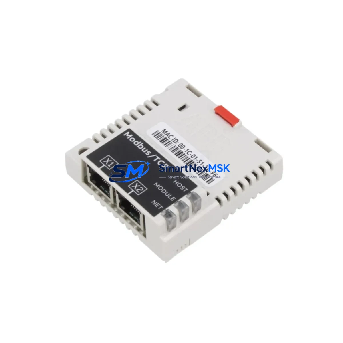
ABB FMBT-21 Retrofit-Ready Modbus/TCP Adapter for ACS Series Control Systems
The ABB FMBT-21 is a Modbus/TCP fieldbus adapter module designed for seamless integration into ABB ACS series variable frequency drives. As a direct retrofit replacement for legacy FDPI-02 drive bus communication interfaces, the FMBT-21 enables industrial facilities to modernize their control architecture without replacing the entire drive system. Whether you are upgrading an aging ACS550, ACS800, or ACS880 installation, or migrating from a proprietary drive bus topology to standard Ethernet-based Modbus/TCP, the FMBT-21 provides a validated, cost-effective upgrade path with minimal disruption to existing production lines.
In retrofit and modernization projects, the FMBT-21 is typically installed into the drive’s option slot D or E, replacing the outgoing FDPI-02 or FDCO-01 fiber-optic communication module. Before installation, engineers must verify the drive’s firmware version supports the FMBT-21 parameter set, confirm that the control panel — such as the ACS-AP-I or ACS-AP-W — remains compatible, and review the existing parameter backup to ensure group 51 (communication module) settings are correctly remapped. The FMBT-21 communicates over standard RJ-45 Ethernet, eliminating the need for proprietary fiber cabling previously required by FDPI-02 installations.
For facilities running distributed I/O architectures, the FMBT-21 integrates cleanly with upstream Modbus/TCP masters such as ABB AC500 PLCs, Siemens S7-300 or S7-1500 controllers, and Schneider Electric Modicon M340 systems. The module supports standard Modbus function codes (FC01, FC02, FC03, FC04, FC06, FC16), enabling read/write access to drive control words, speed references, actual values, and fault registers without custom protocol mapping.
Upgrade Compatibility Table
| Parameter | FDPI-02 (Legacy) | FMBT-21 (Retrofit) |
|---|---|---|
| Communication Protocol | ABB Drive Bus (Proprietary Fiber) | Modbus/TCP over Ethernet (RJ-45) |
| Physical Interface | Fiber Optic (FDCO-01 compatible) | RJ-45 Ethernet (10/100 Mbps) |
| Drive Compatibility | ACS550, ACS800 (legacy firmware) | ACS550, ACS800, ACS880, ACS580 |
| Option Slot | Slot D / E | Slot D / E (direct fit) |
| Parameter Group | Group 51 (legacy mapping) | Group 51 (remapped, firmware ≥ 2.x) |
| IP Address Configuration | Not applicable | Static or DHCP via drive panel or PC tool |
| HMI Panel Compatibility | CDP312R, ACS-AP-I | ACS-AP-I, ACS-AP-W (firmware update may be required) |
| Commissioning Tool | DriveWindow 2 | Drive Composer Pro / DriveWindow 2 |
| Retrofit Complexity | — | Low — plug-in module, parameter restore |
| Warranty | — | 12-Month Warranty (SMARTNEXMSK) |
Retrofit Planning for Existing Automation Systems
A successful FMBT-21 retrofit begins with a thorough audit of the existing control cabinet. Engineers should document the current wiring of the XPOW power supply terminals, verify that the drive’s 24 VDC auxiliary power rail can support the additional module load, and confirm that the backplane slot is physically unobstructed. In multi-drive installations — for example, a line of ACS800 drives connected via an NDBU-95 branching unit — each drive’s FMBT-21 must be assigned a unique Modbus device address (1–247) to prevent bus conflicts.
During the planning phase, it is equally important to review the existing PROFIBUS DP or DeviceNet topology if the facility is simultaneously migrating from legacy fieldbus to Modbus/TCP. In such cases, the FMBT-21 may be deployed alongside an FPBA-01 PROFIBUS adapter on a parallel drive, allowing phased migration without a full system cutover. Terminal block wiring for the drive’s digital I/O — typically routed through XTIO and XTAI terminal rows — does not require modification during the FMBT-21 installation, which significantly reduces rewiring time.
For ACS880 installations with an AIMA-01 inverter module or AINT-02 control board, engineers should confirm that the drive’s option module firmware is current before inserting the FMBT-21. The Drive Composer Pro software provides a guided parameter wizard that maps legacy FDPI-02 communication parameters to their FMBT-21 equivalents, reducing manual parameter entry errors. Where an NETA-21 remote monitoring adapter is already installed, the FMBT-21 can coexist in a separate option slot, enabling simultaneous Modbus/TCP control and remote diagnostics without conflict.
Facilities that rely on ABB Panel Builder or third-party SCADA systems for HMI visualization should update their Modbus register maps to reflect the FMBT-21’s address layout. Drive status words, fault codes, and speed feedback registers retain the same logical meaning but may shift in absolute Modbus register address depending on the firmware version. Pre-commissioning register mapping verification using a Modbus poll tool is strongly recommended before returning the drive to automatic control.
Downtime Control During System Migration
Minimizing production downtime is the primary concern in any drive communication retrofit. The FMBT-21 installation procedure is designed to be completed within a single planned maintenance window, typically 2–4 hours per drive, depending on cabinet accessibility and parameter complexity. The recommended sequence is: (1) perform a full parameter backup using Drive Composer Pro or DriveWindow 2 before powering down; (2) remove the legacy FDPI-02 or FDCO-01 module from the option slot; (3) insert the FMBT-21 and restore power; (4) configure the IP address and Modbus device ID via the ACS-AP-I panel; (5) restore the parameter backup and verify group 51 settings; (6) perform a communications test from the PLC or SCADA master before releasing the drive to production.
To protect existing program logic, engineers should export the PLC program from the upstream controller — whether an ABB AC500, Siemens S7, or Allen-Bradley ControlLogix — and verify that all Modbus read/write function blocks reference the correct new register addresses before going live. Where possible, a shadow test using a spare drive or a hardware-in-the-loop simulator is advisable for critical process lines. Field control continuity can be maintained by keeping the drive in local hand mode during the communication switchover, ensuring that motor speed and direction are not interrupted by the protocol migration.
SMARTNEXMSK ships all FMBT-21 units pre-tested and serialized, with a factory test report included. Each unit undergoes power-on verification, Ethernet link negotiation testing, and Modbus register read/write validation before dispatch. This pre-shipment testing protocol reduces on-site commissioning risk and supports faster return to automatic operation. All units are covered by a 12-month warranty from the date of shipment, with technical support available for installation and parameter configuration queries.
Retrofit Support FAQ
Q1: Is the FMBT-21 a direct drop-in replacement for the FDPI-02?
The FMBT-21 occupies the same option slot (D or E) as the FDPI-02 and uses the same mechanical form factor, making physical installation straightforward. However, because the FMBT-21 uses Modbus/TCP over Ethernet rather than the proprietary ABB Drive Bus fiber protocol, the upstream PLC or SCADA system must be reconfigured to communicate via Modbus/TCP. Parameter group 51 must also be remapped to the FMBT-21’s register layout. SMARTNEXMSK provides a parameter migration checklist upon request.
Q2: What wiring changes are required in the control cabinet?
The primary wiring change is the addition of a standard Cat5e or Cat6 Ethernet cable from the FMBT-21’s RJ-45 port to the facility’s Ethernet switch or directly to the PLC’s Ethernet port. The existing FDPI-02 fiber optic cables (connected to FDCO-01 or NDBU-95 branching units) are removed. All other terminal wiring — including XTIO digital I/O, XTAI analog input, and XPOW power supply terminals — remains unchanged, significantly reducing rewiring labor.
Q3: How is compatibility with the existing HMI verified before commissioning?
Before commissioning, verify that the drive’s control panel firmware (ACS-AP-I or ACS-AP-W) is updated to a version that supports the FMBT-21 parameter set. Use Drive Composer Pro to run a parameter consistency check after restoring the backup. For SCADA or DCS systems, perform a Modbus register poll test using a diagnostic tool to confirm that all required drive status, control, and reference registers are accessible and returning expected values before switching the drive from local to remote control mode.
Q4: What does the 12-month warranty cover, and what is the return process?
The 12-month warranty covers manufacturing defects, component failures, and communication interface faults under normal operating conditions. It does not cover damage resulting from incorrect installation, overvoltage, or environmental contamination. To initiate a warranty claim, contact SMARTNEXMSK with the unit serial number and a description of the fault. Replacement units are dispatched within 3–5 business days after fault verification. Pre-shipment test reports are available for all warranty replacement units.
© 2026 SMARTNEXMSK. All rights reserved.
Original Source: https://smartnexmsk.com
Contact: [email protected] | +86 18259474341



