
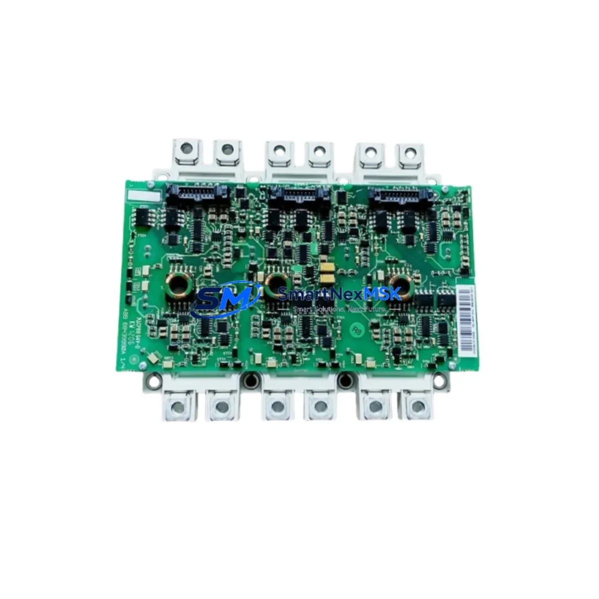
ABB FS300R12KE3/AGDR-71C Retrofit-Ready IGBT Kit for ACS800 & ACS880 Control Systems
The ABB FS300R12KE3/AGDR-71C is a high-performance IGBT power module and gate driver assembly engineered for seamless retrofit integration into ABB ACS800 and ACS880 series variable frequency drives. Rated at 300A / 1200V, this kit is the factory-specified replacement for R7 and R8 frame drives and represents the most reliable path for restoring discontinued or aging drive hardware without replacing the entire control cabinet.
Industrial facilities operating legacy ACS800 drives — particularly those running on firmware platforms such as RDCU-02C or RMIO-11C control boards — frequently encounter IGBT failure as the primary cause of unplanned downtime. The FS300R12KE3/AGDR-71C addresses this directly: the AGDR-71C gate driver board is pre-matched to the FS300R12KE3 module, eliminating the compatibility risk that arises when sourcing components separately. Engineers performing the swap must verify DC bus capacitor condition, confirm that the AINT-02C or AINT-14C interface board is intact, and check that the PPCS fiber-optic communication link between the control unit and the inverter bridge is undamaged before powering up.
For ACS880 retrofit projects — particularly those involving the ACS880-07 cabinet drive or ACS880-17 regenerative variants — the same IGBT kit applies to R7/R8 frame configurations. Technicians should confirm that the ACS880 control program (e.g., IEC 61131-3 application programs stored on the ZMU-02 memory unit) is backed up prior to any hardware intervention. The IGBT swap itself does not alter drive parameters, but a full parameter restore from the BCU-12 or BCU-22 control unit backup is recommended as a precaution.
Upgrade Compatibility Table
| Attribute | Detail |
|---|---|
| SKU | FS300R12KE3/AGDR-71C |
| Brand | ABB |
| Compatible Drive Series | ACS800 (R7/R8), ACS880 (R7/R8) |
| Voltage Rating | 1200V |
| Current Rating | 300A |
| Gate Driver Included | Yes — AGDR-71C |
| Frame Size | R7 / R8 |
| Mounting Interface | Direct bolt-in to existing heatsink bracket |
| Communication Compatibility | PPCS fiber-optic (compatible with AINT-02C, AINT-14C) |
| Replaces Discontinued Part | Yes — original FS300R12KE3 EOL; this kit is the current replacement |
| Retrofit Recommendation | Replace as a matched pair (module + gate driver) for optimal reliability |
| Commissioning Note | Verify DC bus discharge, torque terminal bolts to spec, re-run ID run after installation |
| Warranty | 12 Months |
Retrofit Planning for Existing Automation Systems
A successful IGBT retrofit begins well before the module arrives on site. The first step is a full audit of the drive cabinet: inspect the RDCU-02C or RMIO-11C control board for corrosion or damaged ribbon connectors, verify that the AINT-02C interface board fiber ports are clean and undamaged, and confirm that the PPCS link to the BCU-12 or BCU-22 control unit is error-free. If the drive is part of a multi-drive system using an NDBU-95C branching unit, the fiber topology must be documented before any hardware is removed.
Terminal wiring is a critical checkpoint. The DC bus busbars connecting to the FS300R12KE3 must be torqued to the manufacturer’s specification — under-torqued connections are a leading cause of premature IGBT failure after retrofit. The U2, V2, W2 output terminals and the DC+ / DC- input connections should be inspected for heat discoloration or micro-arcing marks. If the existing AGDR-71C gate driver shows signs of thermal stress, it must be replaced alongside the power module — never reuse a suspect gate driver with a new IGBT.
For facilities also upgrading their I/O architecture, this retrofit window is an ideal time to audit RAIO-01 analog I/O extension modules and RDIO-01 digital I/O modules for firmware compatibility with the updated drive. If the control system interfaces with a Profibus DP network via an RPBA-01 adapter or a PROFINET link via an RETA-02 Ethernet adapter, communication parameters should be exported and verified before the drive is taken offline. Panel-mounted HMI units — such as those running ABB’s CDP312R control panel — should have their parameter sets saved locally before the retrofit begins, as a precaution against accidental parameter loss during power cycling.
Where the retrofit is part of a broader migration from ACS800 to ACS880 architecture, engineers should note that the ACS880 uses a different application programming environment (Drive Composer Pro vs. DriveWindow 2) and that existing ACS800 application macros cannot be directly imported. The ZMU-02 memory unit on the ACS880 stores the full parameter set and application program, and its contents should be verified post-retrofit before the drive is returned to service.
Downtime Control During System Migration
Minimizing production downtime during an IGBT retrofit requires a structured pre-outage preparation protocol. Before the scheduled maintenance window, the replacement FS300R12KE3/AGDR-71C kit should be bench-tested for gate signal integrity using a gate driver tester or oscilloscope — this confirms the unit is functional before it enters the cabinet. A full parameter backup from the BCU-12 or BCU-22 control unit should be stored on a laptop running Drive Composer Pro or DriveWindow 2, with a secondary copy on a USB drive kept at the control panel.
During the outage, the DC bus must be fully discharged and verified with a calibrated voltmeter before any work begins — residual DC bus voltage in R7/R8 frame drives can exceed 800V and is lethal. The IGBT module swap itself typically takes 45–90 minutes for an experienced technician; the majority of the outage time is consumed by discharge waiting periods, torque verification, and post-installation commissioning. After the new module is installed, an ID run (motor identification run) should be performed to re-optimize the drive’s current control parameters for the connected motor.
To protect original program logic, the RDCU-02C or BCU-22 control board should remain powered (if safe to do so via a separate 24VDC supply) throughout the IGBT swap, preserving volatile memory contents. If the control board must be de-energized, the parameter restore procedure should be rehearsed in advance. Keeping a pre-tested spare AGDR-71C gate driver on the shelf alongside the FS300R12KE3 module is strongly recommended for facilities where this drive frame is critical to production continuity.
Retrofit Support FAQ
Q1: Is the FS300R12KE3/AGDR-71C a direct drop-in replacement for the original ABB IGBT kit in ACS800 R7/R8 drives?
Yes. The FS300R12KE3/AGDR-71C is the current factory-recommended replacement for the original IGBT assembly in ACS800 and ACS880 R7/R8 frame drives. The mechanical mounting pattern, DC bus busbar interface, and gate driver connector are identical to the original specification. No drive parameter changes are required solely for the IGBT replacement, though an ID run is recommended after installation.
Q2: What commissioning steps are required after installing the new IGBT module?
After installation, verify all terminal torque values, confirm the PPCS fiber-optic link is active (no fault on the AINT-02C or AINT-14C board), and perform a no-load power-up to check for gate driver fault codes. If the drive passes the no-load test, perform a full motor ID run before returning the drive to production. Log the commissioning date and technician details for warranty records.
Q3: Can the existing wiring and terminal block layout be reused during the retrofit?
In most cases, yes. The FS300R12KE3 uses the same busbar bolt pattern as the original module, so DC bus and output phase connections can be reused without modification. However, inspect all busbars and terminal hardware for heat damage or corrosion before reuse. If the AGDR-71C gate driver ribbon cable shows any cracking or delamination, replace it with a new cable — do not reuse damaged signal wiring.
Q4: What does the 12-month warranty cover, and how is it validated?
The 12-month warranty covers manufacturing defects and premature failure under normal operating conditions. Each unit shipped by SMARTNEXMSK undergoes pre-shipment functional testing, and a test report is included with the delivery. To validate a warranty claim, retain the original invoice, the pre-shipment test report, and the commissioning log. Warranty claims must be submitted to [email protected] within the 12-month period from the invoice date.
© 2026 SMARTNEXMSK. All rights reserved.
Original Source: https://smartnexmsk.com
Contact: [email protected] | +86 18259474341



