
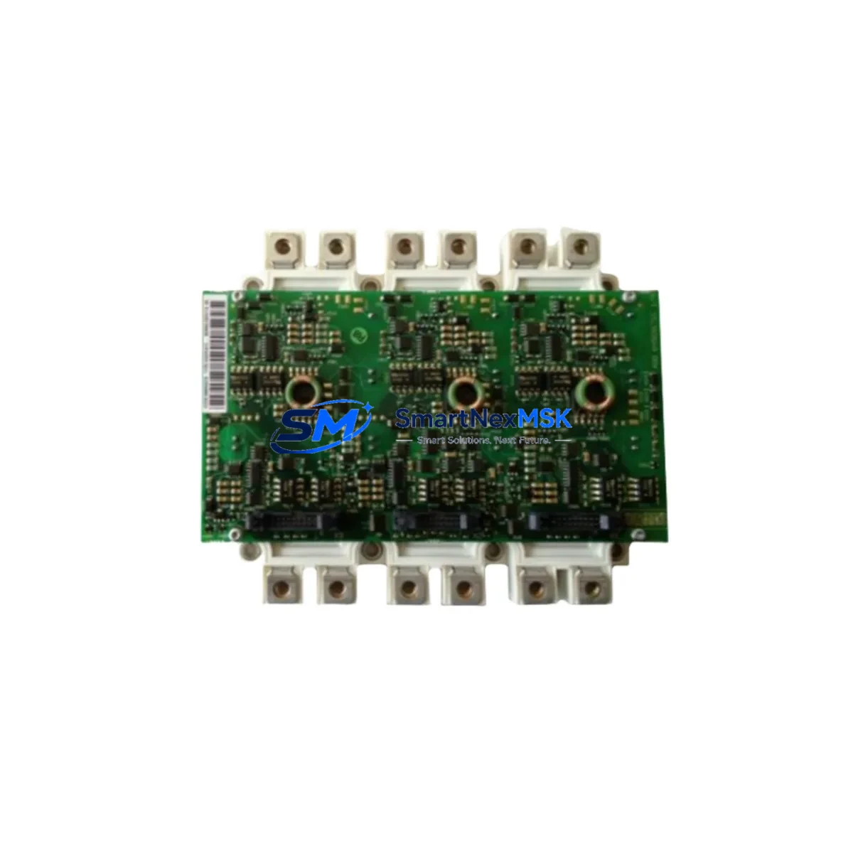
ABB FS300R12KE3/AGDR-72CS Retrofit-Ready IGBT Module for EconoPACK+ Control Systems
The ABB FS300R12KE3/AGDR-72CS is a high-performance 1200V / 300A IGBT power module designed for demanding industrial drive and power conversion applications. Packaged in the industry-standard EconoPACK+ form factor, this module integrates the FS300R12KE3 IGBT stack with the AGDR-72CS gate driver board, delivering a complete, retrofit-ready solution for engineers upgrading aging variable frequency drives (VFDs), servo amplifiers, and medium-voltage converter cabinets. Whether you are replacing a failed unit on an existing production line or executing a planned modernization of legacy power electronics, this assembly provides a verified drop-in upgrade path with minimal downtime.
Industrial facilities running older ABB ACS800, ACS600, or third-party drive platforms frequently encounter obsolescence challenges when the original IGBT modules reach end-of-life. The FS300R12KE3/AGDR-72CS addresses this directly: its EconoPACK+ footprint ensures mechanical compatibility with standard heatsink mounting patterns, while the AGDR-72CS gate driver maintains the signal-level interface expected by most legacy drive control boards. Before installation, engineers should verify DC bus voltage rating, gate signal voltage levels (typically ±15V), and the current sense output scaling to confirm compatibility with the existing control PCB.
Upgrade Compatibility Table
| Parameter | FS300R12KE3/AGDR-72CS | Typical Legacy Module | Notes |
|---|---|---|---|
| Collector-Emitter Voltage (Vces) | 1200V | 1200V | Direct match for standard 690V AC drive applications |
| Continuous Collector Current (Ic) | 300A | 200–300A | Verify thermal derating at ambient temperature |
| Package Format | EconoPACK+ | EconoPACK / EconoPACK+ | Confirm heatsink hole pattern before ordering |
| Gate Driver | AGDR-72CS (integrated) | Separate or integrated | Check fiber-optic or direct gate signal interface |
| Mounting Torque | 3–4 Nm | 3–4 Nm | Use calibrated torque wrench; apply thermal paste |
| Communication Compatibility | Analog gate signal | Analog / fiber-optic | AGDR-72CS supports HFBR fiber-optic input option |
| Commissioning Focus | Gate delay, deadtime, desaturation threshold | Varies by OEM | Reconfigure drive parameters after replacement |
| Warranty | 12-Month Warranty — All units tested before shipment | ||
Retrofit Planning for Existing Automation Systems
A successful retrofit of the FS300R12KE3/AGDR-72CS begins well before the module arrives on site. Start by auditing the existing drive cabinet: confirm the DC bus capacitor bank condition, check the pre-charge resistor and relay circuit, and inspect the gate driver power supply rails (typically ±15V isolated). If the cabinet uses an ABB RDCU-02C or RDCU-12C control unit, verify that the PWM output signals are within the AGDR-72CS input specification. For drives using fiber-optic gate links, confirm that the HFBR-1521 transmitter and HFBR-2521 receiver pair on the existing control board are functional before condemning the power module.
In multi-axis or parallel inverter configurations, the replacement module must be matched in threshold voltage (Vge(th)) and transconductance to the remaining modules to ensure balanced current sharing. It is common practice to replace all modules in a phase leg simultaneously. When working on an ABB ACS800 drive, the AINT-02C or AINT-12C interface board and the APOW-01C auxiliary power supply should be inspected as part of the same service event, since these components are subject to similar thermal aging cycles as the IGBT module itself.
Terminal wiring adaptation is straightforward for EconoPACK+ replacements: the DC+ and DC− bus bars connect to the module’s collector and emitter terminals using M8 bolts, while the AC output phase terminal connects to the load-side bus bar. Confirm bus bar alignment and insulation clearance before torquing. The AGDR-72CS gate driver ribbon cable or fiber-optic connector should be routed away from high-dV/dt conductors to prevent noise coupling. If the original installation used an ABB NBRA-653 braking chopper module in the same cabinet, inspect its gate driver and snubber circuit as part of the same maintenance window.
For systems incorporating an ABB ACS550 or ACS355 drive with an external brake resistor and an MFDT-01 fieldbus adapter, the retrofit scope may extend to reconfiguring the drive’s motor control parameters after the power module replacement. Always back up the drive parameter set using DriveWindow or the ACS control panel before beginning work. If the site uses a CP600 or CP620 HMI panel connected via PROFIBUS-DP or Modbus RTU, verify that the communication link remains active during the module swap by using a bypass or hot-standby arrangement where the process permits.
Downtime Control During System Migration
Minimizing production downtime during an IGBT module replacement requires a structured pre-outage preparation protocol. Before the scheduled maintenance window, stage all replacement components — including the FS300R12KE3/AGDR-72CS module, thermal interface material, torque wrench, and a calibrated DC hipot tester — at the work site. Download and print the drive’s current parameter list and fault history log. If the process line has a bypass contactor arrangement, test it under load at least one week before the outage to confirm it is operational.
During the outage, follow a strict sequence: isolate and lock out the drive, discharge the DC bus to below 50V (verified with a calibrated meter), remove the failed module, clean the heatsink surface, apply fresh thermal compound, install the FS300R12KE3/AGDR-72CS, reconnect gate driver and power terminals, and perform a static gate test before re-energizing. The AGDR-72CS includes a desaturation protection circuit that will trip on first power-up if the gate threshold is not correctly set — adjust the Vge(th) trim potentiometer on the driver board as required by the ABB commissioning guide.
After re-energization, run the drive at reduced load (20–30% of rated current) for a minimum of 30 minutes while monitoring module case temperature with an infrared thermometer. Confirm that the drive’s overcurrent and overtemperature protection thresholds are correctly set before returning the system to full production load. Document the replacement in the site’s maintenance management system, including the module serial number, installation date, and thermal compound batch number, to support future warranty claims and predictive maintenance scheduling.
Retrofit Support FAQ
Q1: Is the FS300R12KE3/AGDR-72CS a direct drop-in replacement for my existing EconoPACK+ module?
In most cases, yes — the EconoPACK+ mechanical footprint is standardized, and the AGDR-72CS gate driver is designed to interface with the same signal levels used by ABB and compatible third-party drive control boards. However, you should verify the gate signal voltage, fiber-optic vs. direct drive interface, and DC bus voltage rating before ordering. Our technical team can assist with compatibility confirmation based on your drive model and existing module part number.
Q2: What commissioning steps are required after installation?
After mechanical installation and terminal reconnection, perform a static gate test using a low-voltage DC source to verify gate-emitter switching. Then power up the drive with the motor disconnected and check for fault codes. Re-enter the motor nameplate parameters and run an auto-tuning routine if the drive supports it. Verify overcurrent trip levels and thermal protection settings before connecting the load. The AGDR-72CS desaturation threshold may require adjustment using the onboard trim potentiometer.
Q3: How do I confirm wiring compatibility before installation?
Compare the terminal layout of the FS300R12KE3/AGDR-72CS with your existing module using the ABB datasheet. Check DC bus bar bolt size (M8), AC output terminal position, gate driver connector type (ribbon cable or fiber-optic), and auxiliary power supply voltage (typically 24V DC for the AGDR-72CS logic supply). If your cabinet uses a custom bus bar arrangement, a mechanical trial fit before final torquing is recommended.
Q4: What does the 12-month warranty cover, and how is it validated?
Every FS300R12KE3/AGDR-72CS unit shipped by SMARTNEXMSK undergoes pre-shipment functional testing, including gate switching verification and insulation resistance measurement. The 12-month warranty covers manufacturing defects and premature failure under normal operating conditions. Warranty claims require the module serial number, installation date, and a description of the failure mode. Units showing evidence of overvoltage, incorrect gate drive voltage, or improper thermal interface installation are not covered under warranty.
© 2026 SMARTNEXMSK. All rights reserved.
Original Source: https://smartnexmsk.com
Contact: [email protected] | +86 18259474341



