
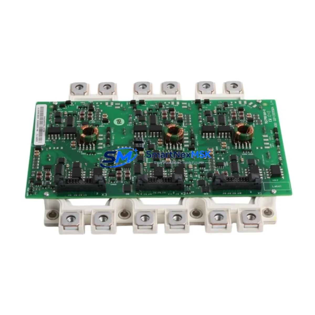
ABB FS450R17KE3/AGDR-71C Retrofit-Ready IGBT Gate Driver for AGDR Series Control Systems
The ABB FS450R17KE3/AGDR-71C is a high-performance IGBT gate driver module engineered for seamless integration into ABB AGDR-series drive and control platforms. As legacy drive systems age and OEM support for discontinued components becomes increasingly difficult to secure, the FS450R17KE3/AGDR-71C has emerged as a critical retrofit solution for engineers tasked with modernizing existing automation infrastructure without full system replacement. Whether you are managing a scheduled upgrade, responding to an unplanned failure, or executing a phased migration from an end-of-life drive platform, this module delivers the electrical compatibility, mechanical fit, and firmware alignment required to restore and sustain production continuity.
Designed to interface directly with ABB’s AGDR-71C gate driver board, the FS450R17KE3 IGBT power module operates at a blocking voltage of 1700V with a continuous collector current rating of 450A, making it well-suited for medium-voltage drive applications in heavy industrial environments including steel processing, paper mills, chemical plants, and large-scale HVAC systems. Its robust thermal interface and standard Econo-PACK mounting footprint allow direct substitution in existing heatsink assemblies, significantly reducing mechanical rework during retrofit operations.
Upgrade Compatibility Table
| Parameter | FS450R17KE3/AGDR-71C | Retrofit Notes |
|---|---|---|
| Blocking Voltage (VCES) | 1700V | Verify bus voltage compatibility with existing DC link design |
| Collector Current (IC) | 450A | Confirm load current profile; derate for ambient temperature above 40°C |
| Gate Driver Board | AGDR-71C | Direct plug-in replacement; verify gate resistor values on driver board |
| Mounting Footprint | Econo-PACK (standard) | Compatible with existing heatsink; re-apply thermal compound on installation |
| Communication Interface | Fiber optic (via AGDR-71C) | Confirm fiber cable routing and optical power levels post-installation |
| Control Platform Compatibility | ABB ACS800, ACS880, ACS6000 | Cross-reference drive firmware version; update if required before commissioning |
| Replacement for Discontinued Models | FS300R17KE3, FS400R17KE3 | Confirm terminal layout and gate drive signal levels match legacy module specs |
| Commissioning Requirement | Drive parameter re-initialization | Run ABB DriveWindow or Drive Composer to verify IGBT identification and fault history clear |
| Warranty | 12 Months | Covers manufacturing defects; includes pre-shipment functional test report |
Retrofit Planning for Existing Automation Systems
A successful retrofit of the FS450R17KE3/AGDR-71C begins well before the module arrives on site. Engineers should start by auditing the existing control cabinet to confirm available DC bus voltage, heatsink condition, and the integrity of the AGDR-71C gate driver board. In many installations, the AGDR-71C itself may show signs of capacitor aging or optocoupler degradation, and it is advisable to replace it alongside the IGBT module to avoid latent failures after restart.
Power supply integrity is a foundational concern. The AGDR-71C requires a stable auxiliary 24VDC supply, typically sourced from the drive’s internal APOW-01 power supply board or an equivalent external rail. Before energizing the new module, verify that the auxiliary supply voltage is within tolerance and that the supply can sustain inrush current during gate driver initialization. If the existing APOW-01 shows signs of wear, replacement should be scheduled as part of the same maintenance window.
Terminal wiring must be carefully documented before disassembly. The FS450R17KE3 uses standard collector, emitter, and gate terminals consistent with the Econo-PACK form factor, but torque specifications must be observed precisely — under-torqued connections are a leading cause of post-retrofit thermal failures. Use a calibrated torque wrench and refer to ABB’s published installation guidelines for terminal tightening sequences.
Backplane and rack interface checks are equally important. In ACS800 and ACS880 drive platforms, the IGBT module communicates indirectly through the AGDR-71C fiber optic link to the AINT-02 or RDCU-02C control boards. Inspect fiber connectors for contamination and verify optical signal strength using a power meter before closing the cabinet. A degraded fiber link is a common source of nuisance IGBT fault trips that can be misdiagnosed as module failure.
Module address configuration is not required for the FS450R17KE3 itself, as addressing is managed at the drive control board level. However, if the retrofit is part of a broader upgrade involving the RDCU-02C or AINT-02 control modules, confirm that the drive’s parameter set correctly identifies the number of parallel IGBT branches and the switching frequency limits appropriate for the new module’s thermal characteristics.
HMI screen updates may be necessary if the existing operator panel — such as an ACS-CP-C or ACS-CP-D control panel — displays drive-specific fault codes tied to the legacy module’s identification data. After module replacement, clear the fault log and perform a full drive identification run to ensure the HMI reflects accurate operational parameters. In systems integrated with ABB’s Ability™ platform or third-party SCADA systems via Modbus RTU or PROFIBUS DP, verify that communication links remain stable after the drive restarts and that no parameter mapping has shifted.
I/O expansion considerations arise when the retrofit is combined with a broader control system upgrade. If the project scope includes adding the RAIO-01 analog I/O extension module or the RDIO-01 digital I/O module to expand process control capability, these should be installed and configured before the final commissioning run to avoid multiple restart cycles. Similarly, if the installation includes an NBRA-12 braking resistor assembly or an NINT-72 fieldbus adapter, confirm that these peripheral modules are compatible with the updated drive firmware version.
Downtime Control During System Migration
Minimizing production downtime during an IGBT module retrofit requires disciplined pre-staging and a clearly defined switchover sequence. Begin by pre-testing the replacement FS450R17KE3/AGDR-71C assembly on a bench setup or spare drive frame before the scheduled maintenance window. This confirms module functionality and eliminates the risk of discovering a defective replacement unit after the production drive has already been de-energized.
Before shutting down the drive, export the full parameter backup using ABB DriveWindow Light or Drive Composer Pro. Store the parameter file on a dedicated USB drive and verify the backup is complete and readable. This step protects the original program logic, motor identification data, and process tuning values, ensuring that post-retrofit commissioning is a restoration rather than a re-engineering exercise.
During the physical swap, follow a strict lockout/tagout procedure and allow sufficient DC bus discharge time — typically a minimum of five minutes after main power isolation, confirmed by voltage measurement at the DC bus terminals. Replace the IGBT module and AGDR-71C gate driver board as a matched pair, re-apply thermal interface compound to the heatsink contact surface, and torque all power terminals to specification.
On restart, bring the drive up in local control mode first, running the motor at reduced speed and load to verify gate drive signals, thermal performance, and fault-free operation before returning to automatic process control. Monitor the drive’s thermal model output and actual heatsink temperature for the first 30 minutes of loaded operation to confirm that the new module’s thermal interface is performing correctly. Once stable operation is confirmed, re-enable remote control and SCADA communication links, and document the completed retrofit in the site maintenance log.
For sites where zero-unplanned-downtime is a contractual requirement, consider maintaining a pre-tested spare FS450R17KE3/AGDR-71C assembly in the site’s critical spares inventory. Our team can supply pre-tested, shelf-ready units with individual test reports, supporting your site’s spare parts strategy and reducing mean time to repair for future events.
Retrofit Support FAQ
Q1: Is the FS450R17KE3/AGDR-71C a direct drop-in replacement for the FS300R17KE3 or FS400R17KE3 in existing ABB drives?
The FS450R17KE3 shares the same Econo-PACK mounting footprint and terminal layout as the FS300R17KE3 and FS400R17KE3, making it mechanically compatible in most installations. However, the higher current rating (450A vs. 300A or 400A) means the gate drive parameters on the AGDR-71C board — particularly gate resistor values — should be verified and adjusted if necessary to match the new module’s switching characteristics. Always perform a drive identification run after installation.
Q2: What wiring checks are required before powering up after module replacement?
Verify DC bus terminal torque, gate and emitter signal wire integrity, auxiliary 24VDC supply voltage, and fiber optic connector cleanliness on the AGDR-71C. Confirm that all safety interlocks and thermistor connections are intact. Measure insulation resistance between power terminals and ground before applying DC bus voltage.
Q3: Does the replacement module come with a functional test report, and what does the 12-month warranty cover?
Yes. Every FS450R17KE3/AGDR-71C unit shipped by SMARTNEXMSK is pre-tested under load conditions and accompanied by an individual test report confirming gate threshold voltage, leakage current, and switching performance. The 12-month warranty covers manufacturing defects and functional failures under normal operating conditions. It does not cover damage resulting from incorrect installation, over-voltage events, or operation outside the module’s rated parameters.
Q4: Can this module be used in a system that has been upgraded from PROFIBUS DP to PROFINET or EtherNet/IP?
The FS450R17KE3/AGDR-71C operates at the power stage level and is protocol-agnostic — it does not directly handle fieldbus communication. Protocol migration is managed at the drive control board level, typically through the NETA-21 remote monitoring tool or a compatible fieldbus adapter module. The IGBT module replacement is fully compatible with drives that have undergone communication protocol upgrades, provided the drive firmware and control board configuration are correctly updated.
© 2026 SMARTNEXMSK. All rights reserved.
Original Source: https://smartnexmsk.com
Contact: [email protected] | +86 18259474341



