
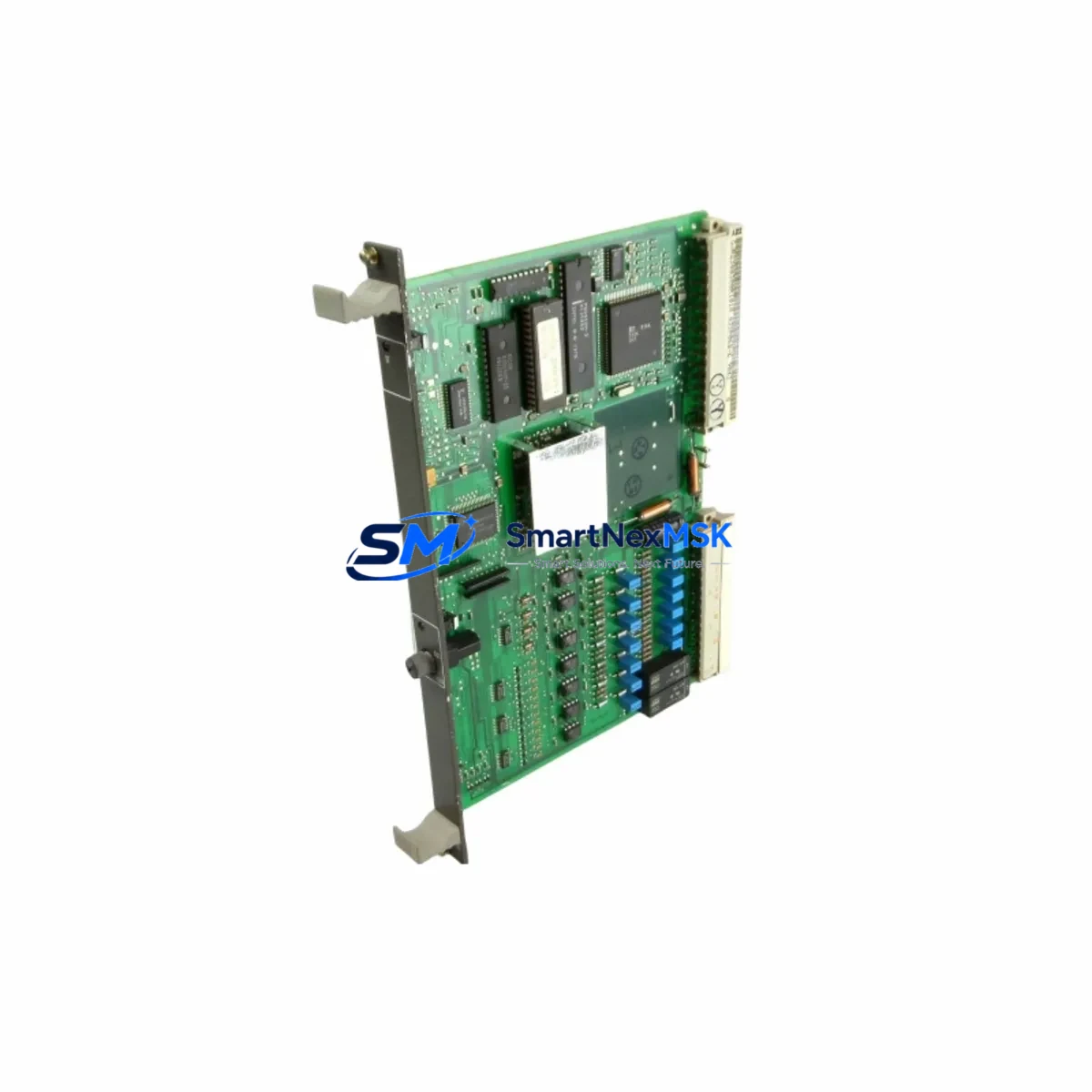
ABB GJR2368900R2340 87TS01I-E Spare for AC800M Automation: Spare Replacement & Industrial Downtime Risk Control
The ABB GJR2368900R2340 (87TS01I-E) is a processor control board designed for the ABB AC800M Distributed Control System (DCS) platform — one of the most widely deployed process automation architectures in power generation, oil & gas, chemical processing, and heavy manufacturing. When this module fails or degrades, the consequences extend beyond a single control loop: the entire AC800M controller node may lose execution capability, triggering process shutdowns, safety interlocks, and unplanned downtime that can cost thousands of dollars per hour.
Stocking a verified, original spare of the GJR2368900R2340 87TS01I-E is the single most effective action a maintenance team can take to protect system uptime. This listing provides a genuine ABB replacement module — tested before shipment, backed by a 12-month warranty, and available for fast worldwide delivery to minimize your mean time to repair (MTTR).
Spare Maintenance Table
| Parameter | Specification / Detail |
|---|---|
| Part Number | GJR2368900R2340 |
| Firmware / Variant | 87TS01I-E |
| Compatible Platform | ABB AC800M DCS (PM860, PM861, PM864, PM866 controller families) |
| Module Function | DCS Processor Control Board — CPU execution, I/O coordination, communication arbitration |
| Mounting | DIN-rail / backplane slot, AC800M controller chassis |
| Power Supply Requirement | Supplied via AC800M backplane (SD821, SD822, SD823 power supply modules) |
| Communication Interfaces | Ethernet (CEX-Bus), RS-232 service port; compatible with CI854 / CI858 fieldbus adapters |
| Operating Temperature | 0 °C to +55 °C (storage: −40 °C to +70 °C) |
| Humidity | 5–95% RH, non-condensing |
| Origin | Germany (ABB Automation GmbH) |
| Condition | Original, new or fully refurbished; tested before shipment |
| Warranty | 12 months from date of shipment |
| Certifications | CE, UL listed (per AC800M platform) |
| Typical Application | Process automation, power plant DCS, refinery control, water treatment SCADA |
| Replacement Compatibility | Direct drop-in for same PN; verify firmware revision with engineering before substituting adjacent revisions |
Maintenance Planning for Continuous Operation
Replacing the GJR2368900R2340 87TS01I-E processor board is rarely an isolated task. Experienced maintenance engineers know that a processor fault in an AC800M node is often preceded — or accompanied — by stress on adjacent components. A disciplined replacement workflow should include inspection and, where appropriate, proactive replacement of the following components within the same control cabinet:
Power Supply Modules (SD821 / SD822 / SD823): The AC800M processor board draws regulated DC power from the backplane power supply. A degraded SD821 or SD823 power supply module can cause intermittent processor resets that mimic firmware faults. Always measure output voltage and ripple before declaring the processor board as the root cause.
Backplane and Rack Assembly (TB820 / TB840): Inspect the TB820 or TB840 backplane for oxidized connector pins, mechanical stress cracks, or contamination. A faulty backplane can corrupt communication between the processor and I/O modules even after a processor swap.
Digital and Analog I/O Modules (DI810, DO810, AI810, AO810): During a planned outage triggered by a processor fault, loop through all installed I/O modules. Verify that DI810 digital input modules and AO810 analog output modules are responding correctly after the processor is restored. Latent I/O faults are frequently masked by the processor alarm.
Fieldbus Communication Adapters (CI854A / CI858): If the AC800M node communicates over PROFIBUS DP or FOUNDATION Fieldbus, inspect the CI854A or CI858 communication interface module. A processor replacement that restores CPU function but leaves a degraded fieldbus adapter will result in continued field device communication errors.
Relay Output Modules and Terminal Blocks: Check relay output modules (RO810, RO820) and associated terminal blocks for contact wear, loose wiring, or thermal discoloration — particularly in high-cycle applications such as motor control or valve actuation circuits.
Signal Isolators and Barriers: In hazardous-area installations, Zener barriers and galvanic isolators in the signal conditioning chain should be tested for isolation integrity whenever a processor module is replaced. Degraded isolators can introduce ground loops that affect analog signal accuracy.
Fuses and Surge Protection: Replace any blown or discolored fuses in the 24 VDC distribution rail. Surge protection devices (SPDs) on I/O signal cables should be inspected for sacrificial element status — a tripped SPD provides no protection and may introduce signal noise.
HMI Communication Link: Verify the Ethernet link between the AC800M controller and the operator workstation (OWS) or engineering workstation (EWS) running ABB 800xA or Freelance. A processor swap may require re-establishing the OPC DA/UA server connection or reloading the controller application from the engineering tool.
Addressing these components during the same maintenance window eliminates the risk of a second unplanned outage within days of the initial repair — a scenario that erodes both maintenance credibility and production throughput.
Site Replacement Workflow
Step 1 — Pre-Replacement Verification: Before removing the GJR2368900R2340 board, export the current controller application and configuration from ABB Control Builder M or 800xA Engineering Studio. Confirm the firmware version of the replacement module matches the installed base. If the replacement carries a different firmware revision, consult ABB release notes for compatibility with your application version.
Step 2 — Safe Isolation: Follow your site’s Lockout/Tagout (LOTO) procedure. The AC800M supports hot-standby redundancy in some configurations — if redundancy is active, initiate a controlled switchover to the standby controller before isolating the faulty node. This eliminates process disruption during the swap.
Step 3 — Module Removal and Inspection: Remove the processor board using the ejector levers. Inspect the backplane connector for bent pins or debris. Clean with dry compressed air if necessary. Record the serial number and firmware label of the removed module for asset tracking.
Step 4 — Installation and Boot Verification: Insert the replacement GJR2368900R2340 87TS01I-E module and secure the locking mechanism. Power on and observe the LED status sequence: a steady green RUN LED confirms successful boot. If the module enters a fault state, connect the RS-232 service port and retrieve diagnostic codes using ABB’s service tool.
Step 5 — Application Download and Loop Check: Download the controller application from the engineering workstation. Perform a loop check on critical I/O channels before returning the process to automatic control. Verify fieldbus device status on all connected CI854A or CI858 adapters.
Step 6 — Documentation: Update the maintenance management system (CMMS) with the replacement date, module serial numbers, and any observations. Schedule the next planned inspection interval per your preventive maintenance (PM) program.
Spare Parts Support FAQ
Q1: What is the expected service life of the GJR2368900R2340 87TS01I-E, and when should I plan for replacement?
ABB AC800M processor modules are designed for long-cycle industrial service, typically 10–15 years under normal operating conditions. However, capacitor aging, thermal cycling, and firmware obsolescence can accelerate degradation in high-ambient-temperature or high-humidity environments. We recommend stocking at least one spare per installed controller node and scheduling proactive replacement at the 10-year mark or upon first indication of intermittent faults.
Q2: How do I verify compatibility before installation?
Confirm the part number (GJR2368900R2340) and firmware variant (87TS01I-E) against your existing module label and ABB’s hardware compatibility matrix for your AC800M system version. If you are running ABB 800xA or Freelance, cross-reference the supported hardware list in your system release notes. Our team can assist with compatibility verification prior to shipment upon request.
Q3: What pre-shipment testing is performed on this module?
Every GJR2368900R2340 87TS01I-E unit is powered on and subjected to functional verification testing before dispatch. Testing includes boot sequence validation, communication port integrity check, and visual inspection for physical damage. A test report is available upon request. The module ships in anti-static packaging with protective end caps.
Q4: What does the 12-month warranty cover, and what is the return process?
The 12-month warranty covers manufacturing defects and functional failures under normal operating conditions. It does not cover damage resulting from incorrect installation, overvoltage events, or physical mishandling. To initiate a warranty claim, contact our support team with the order number, fault description, and photos of the module and installation environment. Replacement or repair will be processed within 5–10 business days of receiving the returned unit.
© 2026 SMARTNEXMSK. All rights reserved.
Original Source: https://smartnexmsk.com
Contact: [email protected] | +86 18259474341



