
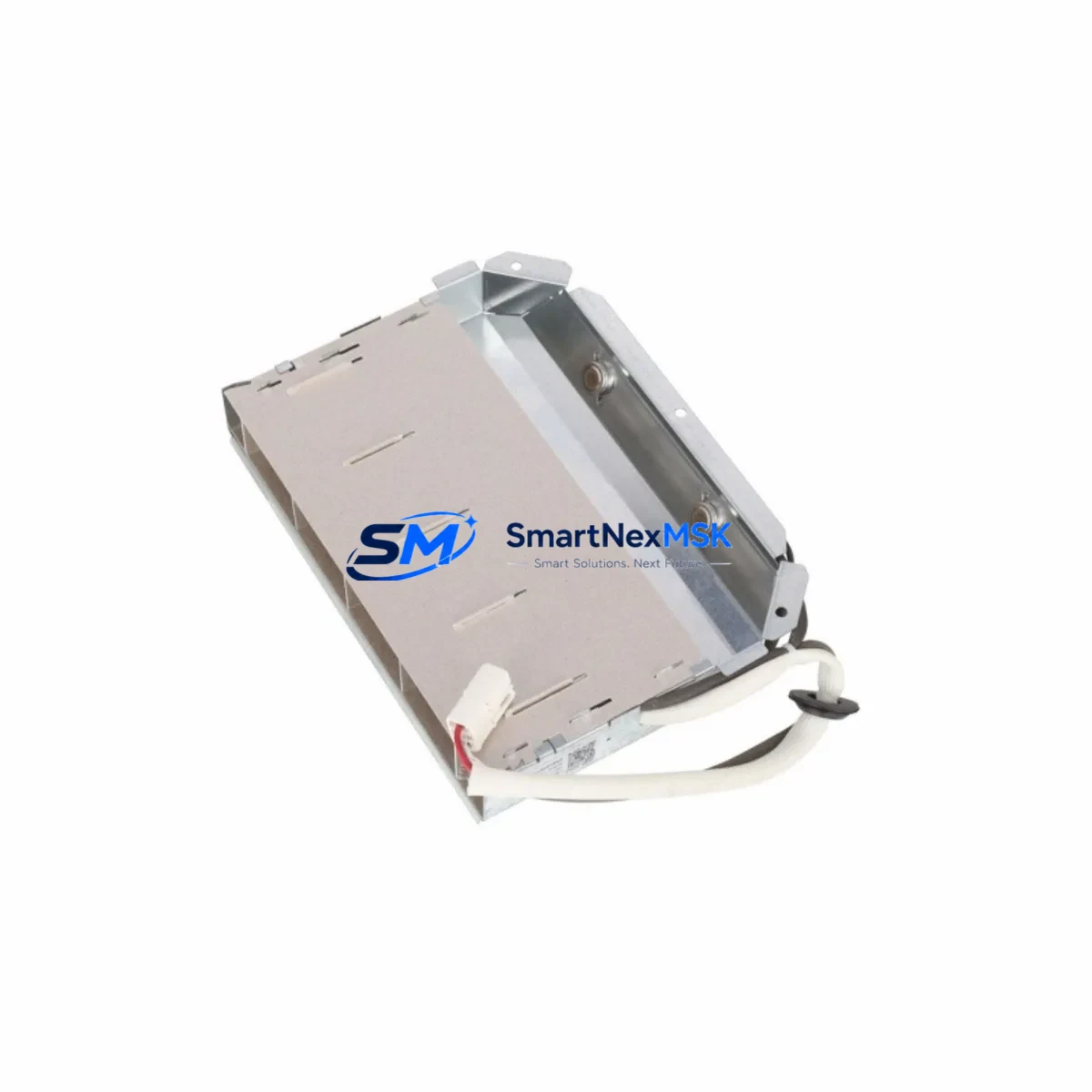
ABB GJR2390200R1211 Retrofit-Ready Relay Output Module for AC500 Control Systems
The ABB GJR2390200R1211 is a relay output module designed for the ABB AC500 PLC platform — one of the most widely deployed modular control systems in industrial automation. As legacy AC500 installations age and original spare parts become increasingly difficult to source, the GJR2390200R1211 serves as a verified retrofit-ready replacement that enables engineers to restore full system functionality without redesigning the control architecture. Whether you are replacing a failed module in a running production line, upgrading an aging control cabinet, or migrating from an earlier AC500 variant, this module delivers the relay switching capacity, terminal compatibility, and firmware alignment required for a smooth, low-risk transition.
The GJR2390200R1211 integrates directly into the AC500 backplane, supporting standard rack mounting alongside companion modules such as the PM573 and PM591 CPUs, the TB521 and TB541 terminal base units, and the DC532 digital input modules commonly found in the same control cabinet. Its relay output channels are rated for both AC and DC load switching, making it suitable for motor starter circuits, solenoid valve control, alarm relay outputs, and safety interlock applications. Each channel is individually fused and optically isolated, ensuring that a field-side fault does not propagate back into the PLC backplane or corrupt adjacent I/O modules.
Before installing the GJR2390200R1211 as a replacement, engineers should verify the following parameters against the existing system documentation: total power budget available on the AC500 power supply module (typically the CP501 or CP502), terminal block wiring assignments on the TB521 or TB541 base, module slot address configured in the PS501 Control Builder software, and the relay output channel mapping defined in the existing PLC program. If the original module was addressed at a specific rack slot, the replacement must occupy the same physical position to avoid I/O address conflicts that would require program modification.
For installations where the original AC500 rack is being expanded or reconfigured, the GJR2390200R1211 can be combined with additional I/O modules such as the AI523 analog input module or the AO523 analog output module to extend the control system’s sensing and actuation capabilities without replacing the CPU or communication infrastructure. This modular expansion approach is particularly valuable in retrofit projects where the goal is to preserve the existing HMI screens, SCADA tag database, and field wiring while selectively upgrading the I/O layer.
Communication continuity is another critical consideration during AC500 retrofit projects. The GJR2390200R1211 operates as a local I/O module on the AC500 backplane and does not require independent communication configuration. However, if the retrofit project also involves migrating from a CS31 fieldbus network to a PROFIBUS-DP or Modbus TCP architecture, the communication coupler modules — such as the CI590-CS31-HA or the CI501-PNIO — must be reconfigured and tested before the relay output module is brought online. Ensuring that the communication link between the AC500 CPU and any upstream SCADA or DCS system remains intact throughout the migration is essential for maintaining production continuity.
All GJR2390200R1211 units supplied by SMARTNEXMSK are sourced from verified industrial channels, individually inspected prior to dispatch, and covered by a 12-month warranty against manufacturing defects and functional failure. Each unit is tested for relay contact integrity, coil actuation response, and backplane connector alignment before shipment. Units are packaged in anti-static protective enclosures with full documentation support available upon request.
Upgrade Compatibility Table
| Parameter | GJR2390200R1211 (This Module) | Notes / Retrofit Guidance |
|---|---|---|
| Series Compatibility | ABB AC500 (V1 & V2 racks) | Verify rack generation before ordering |
| Terminal Base | TB521 / TB541 | Must match existing base in cabinet |
| Output Type | Relay (NO/NC contacts) | Suitable for AC/DC load switching |
| Output Channels | 8 relay outputs | Map channels to existing PLC program tags |
| Rated Load Voltage | Up to 250V AC / 30V DC | Confirm field-side voltage before wiring |
| Backplane Interface | AC500 standard backplane bus | Slot position must match original address |
| Programming Software | PS501 Control Builder Plus | No program changes required if slot is preserved |
| Communication Protocol | Local I/O (no fieldbus config needed) | Fieldbus coupler configured separately |
| Installation Method | DIN rail / rack mount via TB base | Snap-fit onto terminal base, no tools required |
| Warranty | 12 Months | Covers manufacturing defects and functional failure |
Retrofit Planning for Existing Automation Systems
Successful retrofit of the GJR2390200R1211 into an existing AC500 installation begins with a thorough audit of the control cabinet. Engineers should document the current rack layout, recording the slot positions of all installed modules including the CPU (PM573 or PM591), power supply (CP501 or CP502), communication couplers (CI590-CS31-HA or CI501-PNIO), digital input modules (DC532), analog input modules (AI523), and any existing relay output modules. This audit forms the baseline for the replacement plan and ensures that the new module is installed in the correct rack position without disrupting adjacent I/O addressing.
Terminal wiring is the most time-sensitive step in any relay output module replacement. The TB521 or TB541 terminal base retains its field wiring even when the module is removed, which significantly reduces rewiring time. Engineers should photograph the existing terminal assignments and cross-reference them against the original wiring diagram before removing the failed module. Once the GJR2390200R1211 is snapped onto the terminal base, the relay output channels are immediately mapped to the same field devices — motor starters, solenoid valves, alarm relays, or interlock circuits — without any rewiring.
If the retrofit project involves replacing multiple modules simultaneously, it is advisable to stage the replacement by module type, starting with the relay output modules before addressing analog I/O or communication couplers. This sequencing allows the control system to be partially restored and tested at each stage, reducing the risk of a full system outage. The PS501 Control Builder software should be used to perform an online comparison between the existing program and the hardware configuration after each module replacement to confirm that all I/O addresses are correctly resolved.
For projects that also involve upgrading the HMI layer — for example, migrating from an older CP600 panel to a CP620 or CP635 touch panel — the HMI tag database should be exported and validated against the updated PLC program before the new panel is commissioned. This ensures that all relay output status tags, alarm acknowledgment screens, and manual override controls are correctly linked to the GJR2390200R1211 channel assignments in the new configuration.
Downtime Control During System Migration
Minimizing production downtime during an AC500 relay output module replacement requires careful pre-staging and a clearly defined switchover sequence. The recommended approach is to prepare the GJR2390200R1211 as a hot-swap candidate by pre-configuring its slot address in the PS501 Control Builder project file before the maintenance window begins. This allows the CPU to recognize the new module immediately upon power-up without requiring a full program download.
During the switchover, the existing PLC program logic should be preserved in its entirety. The relay output channel assignments, timer settings, interlock conditions, and safety relay configurations defined in the original program remain valid for the GJR2390200R1211 because the module maintains the same I/O address structure as its predecessor. Engineers should avoid modifying the program during the hardware replacement to prevent introducing logic errors that could complicate post-installation troubleshooting.
Field continuity can be maintained by placing the affected relay output channels in a forced-off state via the PS501 software before removing the original module. This prevents uncontrolled switching of connected field devices — such as motor starters or solenoid valves — during the module swap. Once the GJR2390200R1211 is installed and the system is powered up, the forced states should be released one channel at a time, with each channel verified against its expected field device response before proceeding to the next. This staged release procedure typically adds less than 15 minutes to the total switchover time but significantly reduces the risk of field-side incidents caused by unexpected relay actuation.
After the module replacement is complete, a full I/O scan should be performed using the PS501 online diagnostics to confirm that all eight relay output channels are reporting correctly and that no communication errors are present on the AC500 backplane. The system should then be run in manual mode for a minimum of 30 minutes before returning to automatic control to allow any transient conditions in the field wiring to stabilize.
Retrofit Support FAQ
Q1: Is the GJR2390200R1211 a direct drop-in replacement for the original ABB AC500 relay output module?
Yes. The GJR2390200R1211 is designed to mount directly onto the TB521 or TB541 terminal base used in standard AC500 rack configurations. The backplane connector, slot addressing, and relay output channel mapping are fully compatible with the existing AC500 hardware and PS501 software environment. No program modifications are required if the module is installed in the same rack slot as the original unit.
Q2: What commissioning steps are required after installing the GJR2390200R1211?
After installation, power up the AC500 rack and use the PS501 Control Builder online diagnostics to verify that the module is recognized at the correct slot address. Perform a channel-by-channel output test by forcing each relay output individually and confirming the expected field device response. Check the relay contact resistance on each channel using a multimeter before returning the system to automatic control. Document the commissioning results for maintenance records.
Q3: Can the GJR2390200R1211 be used in an AC500 system that has been upgraded to a newer CPU generation?
Yes. The GJR2390200R1211 is compatible with both first-generation and second-generation AC500 CPUs, including the PM573, PM591, PM592, and PM595 processor modules, provided that the terminal base (TB521 or TB541) and rack generation are consistent. If the CPU has been upgraded to a V2 rack configuration, confirm that the terminal base version matches the new rack before installing the module.
Q4: What does the 12-month warranty cover, and how is it claimed?
The 12-month warranty covers manufacturing defects, relay contact failure, backplane connector faults, and any functional failure that occurs under normal operating conditions within the rated electrical and environmental specifications. To claim warranty service, contact SMARTNEXMSK at [email protected] with the order reference number, a description of the fault, and photographic evidence of the installation. Replacement units are dispatched within 3 business days of warranty claim approval.
© 2026 SMARTNEXMSK. All rights reserved.
Original Source: https://smartnexmsk.com
Contact: [email protected] | +86 18259474341



