
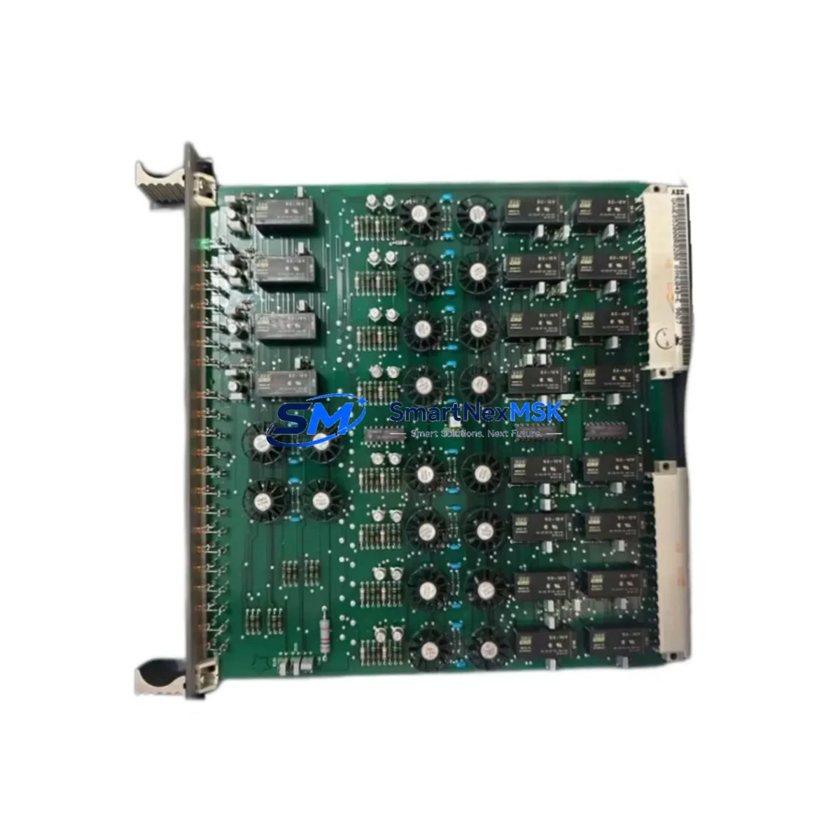
ABB GKW853000R0200 89NU04A-E Retrofit-Ready Drive Control Board for ACS/DCS Control Systems
The ABB GKW853000R0200 89NU04A-E is a drive control board engineered for seamless integration into legacy ABB ACS and DCS series variable frequency drive platforms. As ABB progressively phases out older drive generations, facilities running ACS 400, ACS 600, ACS 800, DCS 400, and DCS 600 series drives face increasing pressure to source reliable replacement boards that maintain original control logic, communication integrity, and I/O mapping without requiring full drive replacement. The GKW853000R0200 89NU04A-E addresses this challenge directly — offering a verified retrofit path that minimizes engineering risk, reduces downtime, and extends the operational life of existing control infrastructure.
This board is manufactured in Finland under ABB’s stringent quality standards and is supplied with a 12-month warranty covering manufacturing defects and functional failures under normal operating conditions. Each unit undergoes pre-shipment functional testing to verify gate drive signals, feedback loop integrity, and communication bus response before dispatch from our Xiamen warehouse.
Upgrade Compatibility Table
| Parameter | Details |
|---|---|
| Compatible Drive Series | ABB ACS 400, ACS 600, ACS 800, DCS 400, DCS 600 |
| Board Function | Drive Control / Gate Drive / Feedback Processing |
| Mounting Interface | Standard ABB backplane slot — direct replacement, no bracket modification |
| Communication Compatibility | DDCS fiber optic link, PROFIBUS-DP (via RPBA-01 adapter), Modbus RTU |
| Terminal Wiring | Matches original X1/X2 terminal block layout; verify 24 VDC auxiliary supply polarity before insertion |
| Firmware / Parameter Set | Retain original parameter backup via DriveWindow or DriveStudio before board swap |
| Replacement Recommendation | Direct drop-in for GKW853000R0200 variants; cross-check suffix revision (A-E) against drive nameplate |
| Commissioning Focus | Re-run autotune after installation; verify speed feedback from RTAC-01 or RTAC-02 pulse encoder module |
| Warranty | 12 months from shipment date — covers manufacturing defects and functional failure under rated conditions |
Retrofit Planning for Existing Automation Systems
Successful retrofit of the GKW853000R0200 89NU04A-E begins well before the board is physically installed. Engineers should first audit the existing drive cabinet to confirm the power supply module — typically an ABB APOW-01 or APOW-02 power supply board — is delivering stable 24 VDC and ±15 VDC rails, as a degraded power supply is a common root cause of repeated control board failures. If the APOW board shows signs of capacitor aging or voltage ripple, it should be replaced concurrently to avoid premature failure of the new control board.
Next, inspect the RMIO-01 or RMIO-02 I/O extension module connections. These modules handle analog and digital I/O routing between the control board and field instruments. Verify that all terminal screws are torqued to specification and that shielded cable grounding is intact at the cabinet entry point. Loose or corroded terminals are a frequent source of nuisance faults after board replacement.
For drives communicating over PROFIBUS-DP, confirm that the RPBA-01 fieldbus adapter is seated correctly and that the GSD file loaded in the PLC master — whether a Siemens S7-300, S7-400, or equivalent — matches the drive’s configured telegram type. If the plant is migrating from PROFIBUS to PROFINET, the RPBA-01 can be replaced with an RETA-02 Ethernet adapter, but this requires corresponding changes to the PLC program and HMI tag mapping.
HMI screens built on ABB Panel Builder or third-party SCADA platforms referencing drive parameters by address should be reviewed against the parameter list of the replacement board. Parameter numbering is generally consistent across ACS 800 firmware versions, but any customized application macros stored in the FLASH memory of the original RMIO board must be re-uploaded via DriveStudio or the ACS 800 control panel (ACS-CP-C or ACS-CP-D) after installation.
For systems using the DDCS fiber optic master-follower link — common in multi-drive crane and winder applications — verify that the fiber cable connectors on both the RDCO-01 or RDCO-02 communication option board and the new control board are clean and fully seated. Contaminated fiber connectors are a leading cause of DDCS link faults that can be misdiagnosed as control board failures.
Rack and backplane integrity should also be confirmed. The ABB ACS 800 drive uses a modular option slot backplane; inspect the edge connector on the backplane for bent pins or oxidation before inserting the replacement board. If the drive chassis is a multi-drive cabinet sharing a common DC bus, ensure the DC bus pre-charge circuit and the BAMU-01 bus adapter module are functioning correctly before energizing the replacement board.
Downtime Control During System Migration
Minimizing production downtime during a drive control board replacement requires a structured approach. Begin by creating a full parameter backup using DriveWindow Light or DriveStudio, saving the file to at least two separate storage locations. Document the current fault history log from the drive panel — this provides a baseline for post-installation comparison and can reveal pre-existing issues unrelated to the control board.
Schedule the physical swap during a planned maintenance window. Power down the drive following the ABB lockout/tagout procedure, wait for the DC bus voltage to discharge below 50 VDC (verify with a calibrated meter at the DC bus terminals), then remove the faulty board by releasing the locking tabs and sliding it out of the backplane slot. Insert the GKW853000R0200 89NU04A-E, restore power, and upload the saved parameter set before running the motor identification routine.
For critical continuous processes where even a brief stop is costly, consider staging a pre-configured spare board with the parameter set already loaded. This reduces the live swap window to under 30 minutes in most ACS 800 installations. After the swap, run the drive in local control mode at reduced speed to verify speed feedback, current regulation, and fault-free operation before returning to remote/automatic control from the DCS or PLC. Keep the original board on-site for at least one production cycle as a fallback, and document the installation date and board serial number for warranty tracking.
Retrofit Support FAQ
Q1: Is the GKW853000R0200 89NU04A-E a direct replacement for earlier suffix revisions such as 89NU04A-C or 89NU04A-D?
A: The -E suffix denotes the current production revision. It is functionally compatible with earlier suffix variants in the same drive platform, but always cross-reference the drive nameplate and the original board part number before ordering. Contact our technical team with your drive serial number for confirmation.
Q2: What commissioning steps are required after installation?
A: Restore the parameter backup, run the motor identification (ID run) in the drive’s commissioning menu, verify speed feedback from the encoder or tachometer, and confirm that all I/O signals — start/stop, speed reference, and fault relay — are responding correctly. Re-test any application macros or PLC interlocks before returning the drive to automatic operation.
Q3: Can this board be used in a drive that communicates via Modbus RTU to a third-party SCADA system?
A: Yes. The GKW853000R0200 89NU04A-E supports Modbus RTU communication via the standard RS-485 port on the RMIO module. Verify baud rate, parity, and station address settings match the SCADA configuration. No additional adapter is required for Modbus RTU.
Q4: What does the 12-month warranty cover, and how is a warranty claim processed?
A: The warranty covers manufacturing defects and functional failures under rated operating conditions for 12 months from the shipment date. It does not cover damage caused by incorrect installation, overvoltage, or environmental contamination. To initiate a claim, contact [email protected] with the order number, board serial number, and a description of the fault. Replacement or repair will be arranged within 5 business days of claim verification.
© 2026 SMARTNEXMSK. All rights reserved.
Original Source: https://smartnexmsk.com
Contact: [email protected] | +86 18259474341



