
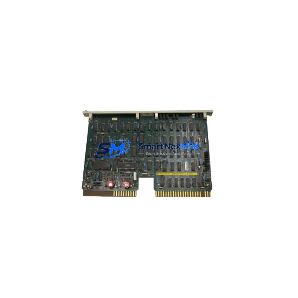
ABB HEDT300867R1 ED1822a Retrofit-Ready Data Interface Board for AC500 Control Systems
The ABB HEDT300867R1 ED1822a is a retrofit-ready Data Interface Board engineered for seamless integration into ABB AC500 PLC control systems. Designed to replace discontinued or aging interface modules in legacy automation architectures, this board delivers full backward compatibility with existing backplane slots, terminal wiring layouts, and communication protocol stacks — enabling plant engineers to execute a controlled upgrade without rewriting core PLC logic or reconfiguring HMI screens from scratch.
Industrial facilities operating legacy AC500 control cabinets frequently encounter obsolescence challenges: original data interface boards reach end-of-life, spare parts become unavailable through standard distribution channels, and unplanned downtime escalates maintenance costs. The HEDT300867R1 ED1822a addresses this directly by providing a verified drop-in replacement path that preserves existing I/O addressing, module slot assignments, and fieldbus communication links — reducing retrofit engineering hours and minimizing production interruption.
Upgrade Compatibility Table
| Parameter | Details |
|---|---|
| Compatible Platform | ABB AC500 PLC Series (PM571, PM581, PM591, PM595) |
| Backplane Interface | Standard AC500 backplane bus connector — direct slot replacement |
| Terminal Wiring | Compatible with existing field wiring; no re-termination required in most installations |
| Communication Compatibility | PROFIBUS DP, Modbus RTU, CANopen — protocol stack preserved |
| Replacement Recommendation | Direct replacement for legacy ED1822a-series data interface boards; verify firmware revision before commissioning |
| Installation Requirement | Power-down rack before insertion; confirm module address DIP switch settings match original configuration |
| Commissioning Focus | Verify I/O mapping in Automation Builder; confirm HMI tag addresses; test communication link continuity |
| Warranty | 12-Month Warranty — covers manufacturing defects and functional failures under normal operating conditions |
Retrofit Planning for Existing Automation Systems
A successful retrofit of the HEDT300867R1 ED1822a into an existing AC500 control system requires systematic pre-installation planning. Before removing the legacy board, engineers should document the current module slot address, record all terminal wiring labels, and export a full backup of the PLC program from the ABB Automation Builder programming environment. This backup protects the original ladder logic, function block diagrams, and variable tables against accidental overwrite during the swap procedure.
Power supply capacity is a critical verification point. The AC500 rack’s PS501 or PS502 power supply module must be confirmed to provide sufficient current headroom for the replacement board alongside all co-installed I/O modules. Overloaded power rails are a common root cause of intermittent faults following retrofit work. Similarly, the TB521 or TB541 terminal base used to mount the interface board should be inspected for contact wear and replaced if corrosion or mechanical damage is present.
Communication architecture must be mapped before commissioning. If the legacy system uses a CM572-DP PROFIBUS master module or a CM575-DN DeviceNet coupler, the network node address assigned to the HEDT300867R1 ED1822a must match the original slave address to avoid bus conflicts. For installations migrating from older serial Modbus RTU links to PROFIBUS DP, a protocol bridge or gateway device may be required to maintain connectivity with downstream field instruments and variable frequency drives.
I/O expansion considerations are equally important. Plants that have added DC532 digital input modules or AX522 analog I/O modules to the original rack configuration must verify that the new data interface board’s firmware supports the expanded I/O count. Address conflicts between newly installed expansion modules and the replacement board can cause silent data errors that are difficult to diagnose without a systematic loop check.
HMI integration is the final pre-commissioning checkpoint. Operators using ABB CP600 or CP620 operator panels connected via Ethernet or serial links must confirm that the HMI project’s communication driver settings — IP address, baud rate, and data format — remain aligned with the replacement board’s default configuration. In most AC500 retrofit scenarios, HMI screen layouts and tag databases require no modification when the replacement board maintains the same data object structure as the original.
Downtime Control During System Migration
Minimizing production downtime during a data interface board replacement is achievable through disciplined pre-staging and a structured hot-swap protocol. The recommended approach is to pre-configure the HEDT300867R1 ED1822a on a bench test rack — using a spare AC500 CPU module and a representative I/O configuration — before the scheduled maintenance window. This allows engineers to validate firmware compatibility, confirm module addressing, and execute a functional communication test without occupying production equipment.
During the actual replacement window, the sequence should follow a defined order: isolate the control cabinet, de-energize the rack, extract the legacy board, insert the HEDT300867R1 ED1822a into the same slot, restore power, and perform a controlled PLC cold start. The original program — backed up prior to the procedure — should be reloaded from the programming terminal running Automation Builder to confirm that all I/O force tables are cleared and all communication links are re-established before returning the system to automatic mode.
For continuous-process installations where even brief interruptions are unacceptable, a parallel redundancy strategy using a secondary AC500 CPU in hot-standby mode can maintain control continuity throughout the board swap. This approach requires that the CM589-PNIO PROFINET I/O coupler or equivalent redundancy module is already present in the control architecture. Post-swap, a full functional test covering all I/O channels, communication links, and HMI displays should be completed and documented before the maintenance record is closed.
All units supplied by SMARTNEXMSK undergo pre-shipment functional testing to verify board initialization, communication port integrity, and backplane bus signaling — reducing the risk of DOA failures during critical retrofit windows. Each unit is covered by a 12-month warranty against manufacturing defects.
Retrofit Support FAQ
Q1: Is the HEDT300867R1 ED1822a a direct drop-in replacement for the original ED1822a board in AC500 systems?
In the majority of AC500 installations, yes. The board maintains the same backplane connector pinout and module slot form factor. However, engineers should verify the firmware revision level using ABB’s compatibility matrix in Automation Builder before commissioning, as certain early AC500 CPU firmware versions may require an update to recognize the replacement board correctly.
Q2: Do I need to re-terminate field wiring when installing the HEDT300867R1 ED1822a?
In most cases, no re-termination is required. The terminal base (TB521 or TB541) remains in place; only the interface board module is swapped. Engineers should inspect terminal contacts for oxidation and confirm that all wiring labels match the original documentation before restoring power.
Q3: How do I verify communication link continuity after installation?
After a cold start, use Automation Builder’s online diagnostic view to confirm that the HEDT300867R1 ED1822a appears in the rack configuration with a green status indicator. For PROFIBUS DP networks, use the CM572-DP master’s diagnostic buffer to confirm that the slave node is responding at the correct address. For Modbus RTU links, a serial analyzer or the CPU’s communication diagnostic counters can confirm frame exchange.
Q4: What does the 12-month warranty cover, and how is a warranty claim processed?
The 12-month warranty covers manufacturing defects and functional failures under normal operating conditions, including backplane interface faults, communication port failures, and board initialization errors. To initiate a claim, contact SMARTNEXMSK at [email protected] with the order reference, installation date, and a description of the observed fault. Replacement units are dispatched after fault verification, with pre-shipment testing completed before dispatch.
© 2026 SMARTNEXMSK. All rights reserved.
Original Source: https://smartnexmsk.com
Contact: [email protected] | +86 18259474341



