
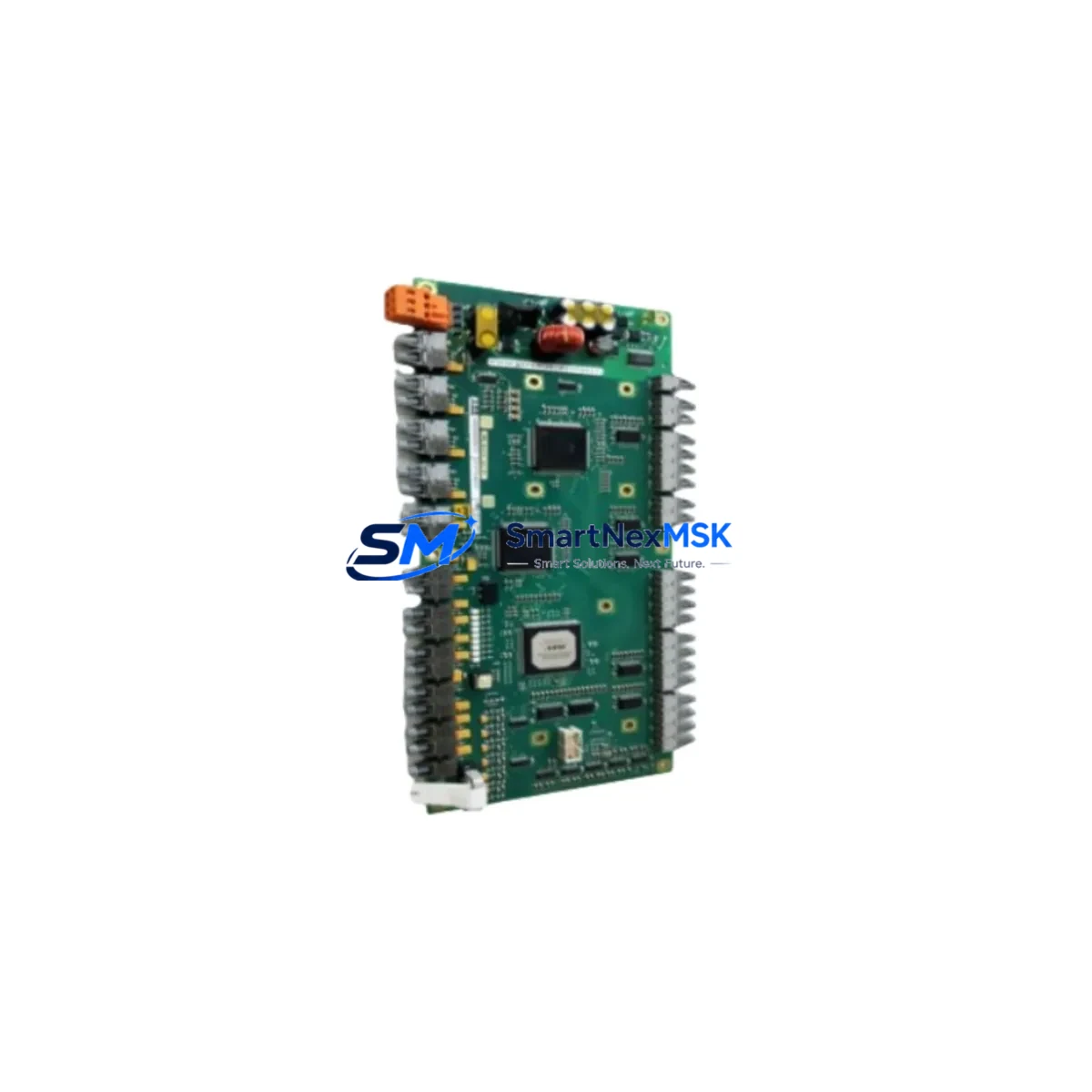
ABB HIER460247R1 UN0806B-P V1 Retrofit-Ready Excitation Control Module for Unitrol Control Systems
The ABB HIER460247R1 UN0806B-P V1 is a precision-engineered excitation control module designed for the ABB Unitrol series of automatic voltage regulators (AVR) and generator excitation systems. As legacy Unitrol installations age and OEM support windows close, this module serves as a verified retrofit-ready replacement that preserves existing wiring configurations, terminal assignments, and backplane interface compatibility — enabling engineers to restore full excitation control without redesigning the control cabinet or rewriting generator protection logic.
Whether you are managing a planned outage at a hydro plant, responding to an unscheduled trip at a gas turbine facility, or upgrading an aging synchronous generator control system at an industrial co-generation site, the HIER460247R1 UN0806B-P V1 is stocked and ready to ship from our Xiamen warehouse with full pre-shipment functional testing and a 12-month warranty.
Upgrade Compatibility Table
| Parameter | Details |
|---|---|
| Compatible Series | ABB Unitrol 1000, Unitrol 1020, Unitrol 5000, Unitrol 6000, Unitrol F |
| Module Function | Excitation regulation, AVR control, reactive power / power factor control |
| Backplane Interface | Standard Unitrol rack backplane — direct slot-in replacement, no adapter required |
| Terminal Wiring | Wiring-compatible with original UN0806B-P terminal layout; verify PT/CT input polarity before energizing |
| Communication Compatibility | Supports MODBUS RTU / RS-485 as used in Unitrol supervisory links; confirm firmware revision with site SCADA |
| Installation Requirement | DIN rail / rack mount per original Unitrol enclosure; no mechanical modification required |
| Replacement Recommendation | Direct replacement for discontinued UN0806B-P V1; suitable for like-for-like swap or controlled upgrade |
| Commissioning Focus | Re-enter AVR gain parameters (Kp, Ki, Kd), verify PT/CT ratios, test manual/auto transfer, confirm PSS settings |
| Pre-Shipment Testing | Full functional test performed on each unit before dispatch |
| Warranty | 12-Month Warranty — covers manufacturing defects and functional failure under normal operating conditions |
Retrofit Planning for Existing Automation Systems
A successful Unitrol excitation system retrofit begins well before the module is physically swapped. Engineers should start by auditing the existing Unitrol rack configuration: identify the power supply module (typically a UN0805A or equivalent Unitrol PSU) and confirm its output voltage and current capacity can support the replacement HIER460247R1 UN0806B-P V1 under full excitation load. Undersized power supplies are a common cause of post-retrofit instability and must be addressed before commissioning.
Next, document all terminal wiring on the existing UN0806B-P V1 before removal. The module interfaces with generator PT (potential transformer) and CT (current transformer) inputs, field current feedback circuits, and digital I/O for AVR mode selection (auto/manual/FCR). Photograph and label every terminal. The Unitrol backplane carries analog measurement signals and internal communication between the AVR module, the I/O expansion modules, and the human-machine interface — typically an ABB CP600 or CP400 series HMI panel. Confirm that the HMI screen tag assignments and alarm setpoints remain valid for the replacement module’s firmware version.
For sites running a redundant excitation configuration — common in large synchronous generators above 10 MVA — the standby channel module (often a second UN0806B-P or a Unitrol channel B card) must be verified for compatibility with the new primary module before the system is returned to service. Mismatched firmware revisions between channel A and channel B can prevent automatic changeover from functioning correctly.
Communication link integrity is equally critical. Many Unitrol installations use MODBUS RTU over RS-485 to report excitation status, reactive power output, and alarm conditions to a plant DCS or SCADA system. After module replacement, verify that the MODBUS device address, baud rate, and register map are correctly configured and that the supervisory system is receiving valid data before releasing the generator to the grid.
I/O expansion is another consideration for aging Unitrol panels. If the existing control cabinet includes Unitrol I/O extension modules for additional digital inputs (protection relay contacts, breaker auxiliary contacts) or analog outputs (field current 4–20 mA retransmission), confirm that these modules remain addressed correctly after the AVR module swap. In some retrofit projects, engineers also take the opportunity to replace aging Unitrol communication gateway modules to improve protocol compatibility with modern DCS platforms.
Finally, ensure that the programming cable and laptop with the appropriate Unitrol commissioning software (e.g., Unitrol Tool or ABB’s AVR configuration utility) are available on-site before the outage window begins. Parameter backup from the old module — if it is still partially functional — can significantly reduce re-commissioning time.
Downtime Control During System Migration
Minimizing generator downtime during an excitation module replacement requires disciplined pre-outage preparation. Before the scheduled maintenance window, back up all AVR parameters from the existing UN0806B-P V1 using the Unitrol commissioning tool. Export the full parameter set including voltage setpoint, droop setting, reactive current compensation, PSS (power system stabilizer) coefficients, and protection thresholds. Store this backup on at least two separate media.
During the outage, follow a structured sequence: isolate the excitation circuit, discharge the field winding, remove the old module, install the HIER460247R1 UN0806B-P V1, restore wiring per the documented terminal layout, and power up the Unitrol rack in manual excitation control mode before switching to automatic voltage regulation. This staged approach protects the original control logic and allows the commissioning engineer to verify each subsystem — PT/CT inputs, field current feedback, HMI communication, and MODBUS link — before the generator is synchronized to the busbar.
For critical generation assets where even a few hours of unplanned downtime carries significant cost, we recommend keeping a pre-tested spare HIER460247R1 UN0806B-P V1 on-site. Our 12-month warranty covers the spare unit from the date of shipment, ensuring your insurance stock remains within warranty coverage throughout a typical annual maintenance cycle.
Retrofit Support FAQ
Q1: Is the HIER460247R1 UN0806B-P V1 a direct drop-in replacement for the original UN0806B-P V1?
Yes. The module is designed as a form-fit-function replacement for the original ABB UN0806B-P V1 used in Unitrol excitation systems. It uses the same backplane connector, the same terminal wiring layout, and the same parameter structure. Minor firmware differences may require re-entry of site-specific AVR gain and protection parameters, which is standard practice for any excitation module replacement.
Q2: What commissioning steps are required after installation?
After physical installation, restore the backed-up parameter set via the Unitrol commissioning tool. Verify PT/CT input ratios, confirm manual/auto transfer operation, check MODBUS communication with the plant SCADA or DCS, and perform a no-load voltage build-up test before synchronizing the generator. If a PSS is active, re-validate PSS gain and phase settings with the protection engineer before returning the unit to service.
Q3: How do I verify wiring compatibility before removing the old module?
Document all terminal connections on the existing UN0806B-P V1 with photographs and a written terminal schedule. Cross-reference against the Unitrol wiring diagram for your specific generator rating and control cabinet revision. Pay particular attention to PT input polarity, CT secondary grounding, and the field current feedback shunt connection — these are the most common sources of commissioning errors during excitation module retrofits.
Q4: What does the 12-month warranty cover, and what is the claims process?
The 12-month warranty covers manufacturing defects and functional failure under normal operating conditions from the date of shipment. If the module fails within the warranty period, contact our technical support team with the order reference and a description of the fault. We will arrange priority replacement dispatch to minimize your site downtime. Warranty does not cover damage caused by incorrect installation, overvoltage events, or operation outside the module’s rated specifications.
© 2026 SMARTNEXMSK. All rights reserved.
Original Source: https://smartnexmsk.com
Contact: [email protected] | +86 18259474341



