
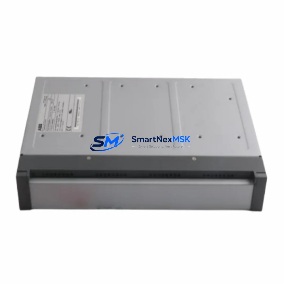
ABB INICT12 Maintenance-Ready Spare for AC500 Automation
The ABB INICT12 is a critical communication interface module within the AC500 PLC platform, designed to facilitate reliable data transfer between the CPU and peripheral control systems. In industrial maintenance environments — from continuous process plants to discrete manufacturing lines — unplanned downtime caused by a failed INICT12 can cascade across entire control loops. Stocking a verified original spare is the single most effective strategy for rapid fault recovery and minimizing mean time to repair (MTTR).
This listing supplies the INICT12 as a maintenance-ready, original ABB spare part. Each unit is sourced through established industrial supply channels, inspected for physical integrity, and function-tested prior to shipment. A 12-month warranty is included, covering manufacturing defects and operational failures under normal service conditions. Whether you are a maintenance engineer executing a planned shutdown replacement or a procurement engineer building a critical-spares inventory, this unit ships ready for immediate installation.
The AC500 platform is widely deployed across energy, water treatment, building automation, and heavy manufacturing sectors. The INICT12 module occupies a central role in the communication architecture of these systems, and its failure — even intermittent — can trigger false alarms, I/O read errors, and CPU communication faults that are difficult to diagnose without a known-good replacement on hand. Experienced maintenance teams treat the INICT12 as a Tier-1 spare: always in stock, always tested, always ready.
Spare Maintenance Table
| Parameter | Specification |
|---|---|
| Part Number / SKU | INICT12 |
| Brand | ABB |
| Series | AC500 |
| Module Type | PLC Communication / Computer Transfer Module |
| Country of Origin | Germany (DE) |
| Compatibility | ABB AC500 PLC family; compatible with PM5xx, PM5x3, PM5x4 CPU modules |
| Mounting | DIN rail / backplane slot installation per AC500 system architecture |
| Operating Temperature | -25°C to +60°C (standard industrial range) |
| Protection Class | IP20 (panel/cabinet installation) |
| Communication Interface | Internal AC500 backplane bus |
| Power Supply | Supplied via AC500 backplane (no external power required) |
| Weight | 260 g |
| Condition | Original, new, factory-sealed or inspected surplus |
| Pre-shipment Test | Yes — function-tested before dispatch |
| Warranty | 12 Months — covers manufacturing defects and operational failure |
| Delivery | Express international shipping available; DHL / FedEx / UPS |
Maintenance Planning for Continuous Operation
When replacing the INICT12 during a scheduled or emergency maintenance event, a thorough inspection of the surrounding control cabinet components is strongly recommended. Communication faults in AC500 systems are rarely isolated — a degraded INICT12 is often accompanied by stress on adjacent modules and wiring.
Begin by verifying the AC500 CPU module (such as the PM554 or PM564) for firmware version compatibility and error log history. Check the 24 VDC power supply module feeding the backplane — voltage sag or ripple is a common root cause of intermittent communication errors that are incorrectly attributed to the INICT12 itself. Inspect the TB521 or TB541 terminal base that the INICT12 seats into; worn or corroded contacts on the terminal base can cause the same symptoms as a failed module.
Review the digital I/O modules (such as the DC532 or DA501) connected downstream of the communication path. If the INICT12 was failing, these modules may have logged unacknowledged faults. Inspect all field wiring and cable shields at the I/O terminal strips — loose shield terminations are a frequent source of noise that accelerates module wear. Check any installed signal isolators or signal conditioners in the analog loops; a failed isolator can inject noise that stresses the communication bus.
If the AC500 system communicates via PROFIBUS DP or Modbus RTU, inspect the fieldbus termination resistors and cable connectors at both ends of the bus segment. A missing or damaged termination resistor will cause bus reflections that degrade communication reliability across all connected nodes. Also verify the CP600 or CP620 HMI panel connection if present — HMI communication errors are often the first visible symptom of a degrading INICT12.
Finally, check the miniature circuit breakers (MCBs) and fuse holders in the control cabinet supply circuit. Nuisance tripping during the fault period may have caused thermal stress on the module. Replacing the INICT12 without addressing upstream power quality issues risks premature failure of the new spare.
Site Replacement Workflow
Step 1 — Preparation: Download the current AC500 project from the CPU using Automation Builder software. Save a timestamped backup. Note the current INICT12 slot position and any parameter assignments in the hardware configuration.
Step 2 — Safe Isolation: Follow your site LOTO (Lockout/Tagout) procedure. De-energize the control cabinet. Confirm zero-energy state with a calibrated voltage tester before opening the enclosure.
Step 3 — Module Removal: Release the INICT12 from its terminal base by pressing the release lever and sliding the module upward. Inspect the terminal base contacts for corrosion or mechanical damage. Replace the terminal base if contact wear is evident — installing a new INICT12 on a worn base is a common cause of repeat failures.
Step 4 — Installation: Seat the replacement INICT12 firmly onto the terminal base until the locking lever clicks. Verify correct slot assignment matches the original hardware configuration in Automation Builder.
Step 5 — Power-Up and Verification: Re-energize the cabinet. Monitor the INICT12 status LED — a steady green indicates normal operation. Use Automation Builder to confirm the module is recognized by the CPU and that no communication errors are present in the diagnostic log.
Step 6 — System Handover: Run a full I/O check across all connected modules. Confirm HMI displays are updating correctly. Document the replacement in your maintenance management system (CMMS) with the new module serial number and installation date.
Spare Parts Support FAQ
Q1: Is this INICT12 an original ABB part or a compatible replacement?
This is an original ABB INICT12 module, not a third-party compatible. It is sourced from authorized industrial supply channels and carries the full ABB part number. Each unit is inspected and function-tested before shipment to confirm it meets OEM specifications.
Q2: What is covered under the 12-month warranty?
The 12-month warranty covers manufacturing defects and operational failures under normal industrial service conditions. It does not cover damage caused by incorrect installation, overvoltage events, or physical mishandling. In the event of a warranty claim, we provide a replacement unit or full refund after fault verification.
Q3: How do I confirm compatibility with my existing AC500 system before ordering?
The INICT12 is compatible with the ABB AC500 PLC family. To confirm compatibility with your specific CPU and terminal base configuration, provide your existing hardware configuration file or the CPU part number when contacting us. Our technical team will verify compatibility before shipment.
Q4: Can you support long-term or blanket purchase orders for critical spare inventory?
Yes. We support scheduled delivery agreements and blanket POs for maintenance teams that require guaranteed stock availability. Contact us to discuss lead times, pricing tiers, and consignment stock arrangements for the INICT12 and other AC500 series components.
© 2026 SMARTNEXMSK. All rights reserved.
Original Source: https://smartnexmsk.com
Contact: [email protected] | +86 18259474341



