
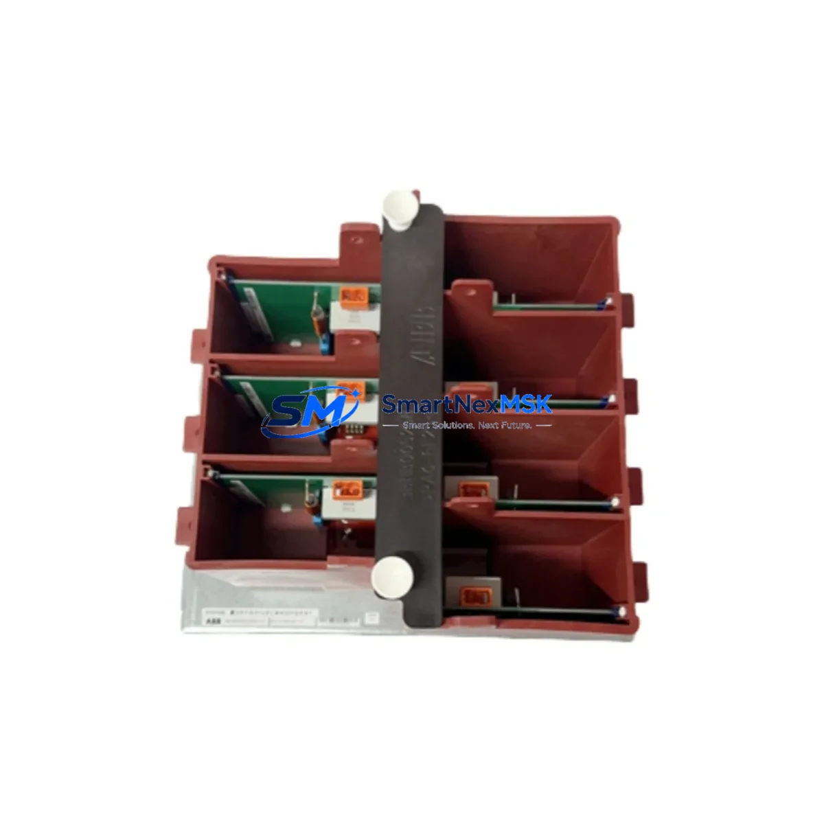
ABB KUC755AE117 Maintenance-Ready Spare for ACS800 Automation
The ABB KUC755AE117 is the original drive control board designed for ABB ACS800 series variable frequency drives (VFDs). In industrial automation environments — from paper mills and cement plants to water treatment facilities and steel rolling lines — the ACS800 drive platform remains one of the most widely deployed medium-power VFD families in the field. When the KUC755AE117 control board fails, the entire drive becomes inoperable, triggering unplanned downtime that can cost thousands of dollars per hour. Stocking this board as a certified maintenance spare is the single most effective step a maintenance team can take to protect ACS800-dependent production lines.
This listing supplies the KUC755AE117 as a genuine original spare, sourced from authorized channels, individually tested before shipment, and backed by a 12-month warranty. Each unit is verified for firmware compatibility, signal integrity, and connector condition prior to dispatch, ensuring that field replacement is a direct swap with no additional commissioning overhead.
Spare Maintenance Table
| Parameter | Specification / Detail |
|---|---|
| Part Number | KUC755AE117 |
| Manufacturer | ABB |
| Compatible Drive Series | ACS800 (single drive and multi-drive cabinet units) |
| Board Function | Main drive control board — speed reference, torque control, I/O management, fieldbus interface |
| Supply Voltage (Logic) | +5 V / ±15 V (supplied internally by APOW power supply board) |
| Fieldbus Interface | Compatible with RDCO-0x DDCS fiber-optic communication modules |
| I/O Capacity | Analog and digital I/O via standard ACS800 I/O terminal blocks |
| Firmware | Factory-loaded; confirm revision compatibility with drive nameplate before installation |
| Operating Temperature | 0 °C to +55 °C (drive cabinet ambient) |
| Mounting | Direct plug-in to ACS800 control section backplane |
| Weight | 560 g |
| Origin | Finland |
| Condition | Original spare — new or recertified, tested before shipment |
| Warranty | 12 months from date of shipment |
| Delivery | Worldwide express; ESD-safe packaging |
| Maintenance Recommendation | Replace proactively at first sign of erratic speed reference, unexplained fault codes (e.g., FF, 0001, 0002), or communication loss with DDCS master |
Maintenance Planning for Continuous Operation
A KUC755AE117 replacement rarely occurs in isolation. Maintenance engineers who have responded to ACS800 drive faults consistently report that the control board failure is often accompanied by — or caused by — degradation in adjacent components. A disciplined site replacement workflow should therefore include inspection and, where warranted, proactive replacement of the following components:
The APOW-01 or APOW-02 power supply board is the first component to check. It provides the regulated +5 V and ±15 V rails that the KUC755AE117 depends on; a marginal APOW board can cause intermittent control board resets that mimic a faulty KUC755AE117. Measure output voltages under load before condemning the control board. Similarly, the AINT interface board (or AINF, depending on drive frame size) sits between the KUC755AE117 and the IGBT gate driver section; connector oxidation or cracked solder joints on the AINT board can introduce spurious fault trips that are misdiagnosed as control board failures.
On the I/O side, inspect the RDIO-01 digital I/O extension module and any RAIO-01 analog I/O extension modules installed in the drive. Corroded terminal blocks or loose field wiring on these modules can generate noise that corrupts the speed reference signal processed by the KUC755AE117. While the drive cabinet is open, verify the condition of the RDCO-01 or RDCO-02 DDCS fiber-optic communication module — cracked fiber connectors or contaminated optical surfaces are a common cause of communication faults between the ACS800 and a master controller or DCS system.
For drives operating in dusty or humid environments, the cabinet cooling fan assembly and air filter mats should be replaced on the same maintenance cycle. Elevated cabinet temperatures accelerate electrolytic capacitor aging on the control board and power supply. Check the DC bus capacitor bank condition using the drive’s built-in capacitor reforming procedure if the drive has been in storage or idle for more than 12 months.
Finally, review the RMIO-11 or RMIO-21 motor control board (where fitted in multi-drive configurations) and any RDNA-01 DeviceNet or RPBA-01 PROFIBUS fieldbus adapter modules. These communication adapters are frequently overlooked during control board replacements but can hold residual fault states that prevent the drive from returning to normal operation after the KUC755AE117 is swapped. A full parameter backup using DriveWindow or Drive Composer prior to any board replacement is strongly recommended.
Site Replacement Workflow
Step 1 — Parameter Backup: Connect a laptop running ABB DriveWindow Light or Drive Composer to the ACS800 panel port. Upload and save the full parameter set. Note the firmware version displayed on the control panel (ACS-CP-C or CDP312R).
Step 2 — Safe Isolation: Open the main incoming isolator and apply lockout/tagout. Wait a minimum of 5 minutes after power-off before opening the drive cabinet door to allow DC bus capacitors to discharge below 50 V (verify with a calibrated multimeter at the DC bus terminals).
Step 3 — ESD Precautions: Don an ESD wrist strap bonded to the drive cabinet chassis before handling the KUC755AE117. The board contains sensitive CMOS components that can be damaged by electrostatic discharge.
Step 4 — Board Removal: Disconnect the ribbon cables and fiber-optic connectors from the KUC755AE117. Note cable routing and connector positions with a photograph before removal. Release the board retaining clips and slide the board out of the backplane.
Step 5 — Replacement Installation: Insert the new KUC755AE117 into the backplane, ensuring all edge connectors are fully seated. Reconnect ribbon cables and fiber-optic connectors in the documented positions.
Step 6 — Firmware and Parameter Restore: Power up the drive and verify that the firmware version on the replacement board matches the backed-up version. Restore the parameter set via DriveWindow or Drive Composer. If firmware versions differ, contact ABB technical support before proceeding.
Step 7 — Functional Test: Run the drive at low speed (10–15 Hz) in local control mode and verify speed reference tracking, analog I/O signals, and fieldbus communication before returning the drive to automatic production control.
This workflow minimizes downtime, preserves system compatibility, and ensures that the replacement board is validated before the production line is restarted.
Spare Parts Support FAQ
Q1: Is the KUC755AE117 compatible with all ACS800 frame sizes?
The KUC755AE117 is the standard control board used across the ACS800 single-drive product family. However, specific hardware revisions (AE117, AE118, etc.) may be tied to particular firmware baselines. Always cross-reference the board revision on the drive nameplate or existing board label with the replacement part before installation. Our technical team can assist with revision compatibility confirmation prior to shipment.
Q2: What testing is performed before shipment?
Every KUC755AE117 unit is powered up on a dedicated ACS800 test rig and subjected to functional verification covering logic power rail integrity, I/O signal response, DDCS fiber-optic communication handshake, and fault-free operation under simulated load conditions. A test report is available upon request. Units are then packed in anti-static bags with foam cushioning for safe international transit.
Q3: How should I manage KUC755AE117 inventory for a multi-drive site?
For sites operating 5 or more ACS800 drives, we recommend maintaining a minimum of one KUC755AE117 spare per 5 drives, with a maximum shelf life of 5 years in climate-controlled storage (15–25 °C, <60% RH). Label each spare with the purchase date and store in original ESD packaging. Rotate stock on a first-in, first-out basis. For critical 24/7 production lines, consider a one-for-one hot spare policy.
Q4: What does the 12-month warranty cover?
The 12-month warranty covers manufacturing defects and functional failures under normal operating conditions from the date of shipment. It does not cover damage resulting from incorrect installation, overvoltage events, physical impact, or operation outside the specified environmental range. In the event of a warranty claim, contact [email protected] with the order number and a description of the fault. Replacement or repair will be arranged within 5 business days of fault confirmation.
© 2026 SMARTNEXMSK. All rights reserved.
Original Source: https://smartnexmsk.com
Contact: [email protected] | +86 18259474341



