
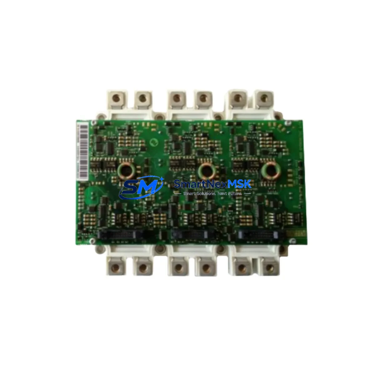
ABB LEC01-R1D-ANR27900560 Retrofit-Ready Control Board for LEC Series Control Systems
The ABB LEC01-R1D-ANR27900560 is a retrofit-ready control board engineered for seamless integration into ABB LEC Series automation and drive control systems. As legacy LEC platform installations approach end-of-life or face discontinued spare parts availability, this module provides a verified drop-in replacement path that preserves existing wiring infrastructure, backplane slot assignments, and program logic without requiring a full system redesign. Whether you are managing a planned upgrade cycle or responding to an unplanned failure on the production floor, the LEC01-R1D-ANR27900560 is stocked and ready for immediate dispatch with a 12-month warranty covering manufacturing defects and functional performance.
Industrial facilities running ABB LEC Series control cabinets often encounter challenges when sourcing original boards for aging installations. The LEC01-R1D-ANR27900560 addresses this directly by maintaining electrical compatibility with the original terminal block layout, preserving the 24 VDC logic supply requirements, and supporting the same backplane communication interface used across the LEC platform family. Engineers responsible for retrofit planning can proceed with confidence knowing that the module has been tested against the original functional specification before shipment.
Upgrade Compatibility Table
| Parameter | LEC01-R1D-ANR27900560 (Replacement) | Original / Legacy Reference |
|---|---|---|
| Module Form Factor | Standard LEC backplane card | Compatible with original LEC rack slot |
| Logic Supply Voltage | 24 VDC ±10% | 24 VDC (original spec) |
| Terminal Wiring | Direct terminal-for-terminal replacement | No rewiring required for standard installations |
| Backplane Interface | LEC Series parallel backplane bus | Fully compatible |
| Communication Protocol | PROFIBUS / Modbus RTU (series-dependent) | Verify active protocol with existing HMI configuration |
| Module Address Setting | DIP switch / rotary selector (as original) | Retain original address before removal |
| Installation Requirement | Power-off hot-swap not supported; controlled shutdown required | Same as original |
| Commissioning | Re-download program if CPU memory cleared; verify I/O mapping | Backup program before replacement |
| Warranty | 12 Months — Manufacturing defects and functional performance | |
Retrofit Planning for Existing Automation Systems
A successful retrofit of the LEC01-R1D-ANR27900560 into an existing control cabinet begins well before the physical swap. The first step is a thorough audit of the control panel’s power budget. The LEC Series power supply module — typically an ABB LEC-PS24 or equivalent 24 VDC rail-mount unit — must have sufficient residual capacity to support the replacement board alongside any co-installed I/O expansion modules. If the existing power supply is already operating near its rated output, a parallel power supply or a higher-capacity replacement should be considered before proceeding.
Terminal wiring documentation is equally critical. Technicians should photograph or transcribe the existing terminal block assignments on the original board before disconnection. The LEC01-R1D-ANR27900560 preserves the standard LEC terminal layout, but field-modified installations may have non-standard wiring that requires individual verification. Pay particular attention to analog input channels, where shielding and grounding practices directly affect signal quality after the swap.
For systems using PROFIBUS DP as the primary fieldbus, the replacement board must be assigned the same station address as the original module. This address is typically set via a rotary switch on the board face. Failure to match the original address will cause the ABB AC500 or S800 I/O master — or whichever PLC CPU is acting as the PROFIBUS master — to report a configuration fault and halt the affected I/O segment. Similarly, installations using Modbus RTU over RS-485 must verify baud rate, parity, and stop bit settings in the HMI configuration, as these parameters are stored in the HMI project and must match the replacement module’s factory defaults or be reconfigured accordingly.
Backplane slot position must be preserved. The LEC Series rack — whether a 4-slot, 8-slot, or 16-slot chassis — assigns logical I/O addresses based on physical slot position. Moving the LEC01-R1D-ANR27900560 to a different slot without updating the PLC program’s I/O mapping will result in incorrect field signal routing. If the original slot is damaged, the program must be updated in the engineering workstation before the new module is commissioned. ABB’s Automation Builder or the legacy Control Builder M software environment is typically used for this task, depending on the CPU generation in service.
Where the control system includes an ABB CP600 or CP400 series HMI panel, technicians should verify that all HMI screen tags referencing the replaced module’s I/O addresses remain valid after the swap. Tag mismatches between the HMI project and the updated PLC program are a common source of post-retrofit alarms. A full HMI simulation run in offline mode before live commissioning is strongly recommended. Programming cables such as the ABB TK503 or USB-to-serial adapters with the appropriate driver set are required for any program download or parameter backup operation during the retrofit window.
Downtime Control During System Migration
Minimizing production downtime during a control board replacement requires a structured pre-outage preparation protocol. Before the scheduled maintenance window, the engineering team should complete a full program backup from the active CPU — including all data blocks, function blocks, and retain-variable areas — and store the backup on an offline engineering station. If the LEC Series CPU supports memory card backup, a card-based copy provides an additional recovery path in the event of an unexpected commissioning issue.
The replacement sequence should be rehearsed in a tabletop walkthrough with the maintenance team, covering the power-down sequence for the control cabinet, the physical removal and installation procedure for the LEC01-R1D-ANR27900560, the address and parameter verification steps, and the controlled power-up sequence. Particular attention should be given to the order in which field devices — sensors, actuators, and drives — are re-enabled after the CPU restarts, to avoid process upsets caused by simultaneous output activation.
For installations where continuous process monitoring is required, a temporary bypass strategy using a portable PLC or a hardwired relay interlock can maintain critical safety interlocks during the swap window. Once the LEC01-R1D-ANR27900560 is installed and the program has been verified online, the bypass can be removed in a controlled sequence. The total planned outage for a straightforward board replacement in a well-documented system is typically 2 to 4 hours, including program verification and I/O checkout. Poorly documented systems or those with field-modified wiring may require additional time for signal tracing and re-verification.
Retrofit Support FAQ
Q1: Is the LEC01-R1D-ANR27900560 a direct drop-in replacement for the original ABB LEC Series control board?
A: Yes, for standard unmodified LEC Series installations. The module preserves the original terminal layout, backplane interface, and logic supply requirements. Field-modified installations should be individually verified against the replacement module’s datasheet before installation.
Q2: Do I need to re-download the PLC program after installing the replacement board?
A: If the CPU retains its program memory during the board swap — which is typical when only the control board is replaced and the CPU module remains powered or retains its memory card — a re-download is not required. However, if the CPU memory is cleared or a new CPU is installed alongside the board, a full program download from the engineering workstation is necessary. Always perform a program backup before beginning any replacement work.
Q3: What commissioning checks are required after installation?
A: After installation, verify the module address setting matches the original, confirm all terminal connections are secure, perform an I/O force test on each channel to verify field signal routing, check communication link status on the PROFIBUS or Modbus segment, and confirm HMI tag values are updating correctly. A full functional test of all associated control loops should be completed before returning the system to automatic operation.
Q4: What does the 12-month warranty cover, and what is the shipping lead time?
A: The 12-month warranty covers manufacturing defects and functional performance failures under normal operating conditions. It does not cover damage resulting from incorrect installation, overvoltage, or environmental conditions outside the module’s rated specification. Units are dispatched from stock within 1–3 business days. Pre-shipment functional testing is performed on every unit before dispatch to confirm operational integrity.
© 2026 SMARTNEXMSK. All rights reserved.
Original Source: https://smartnexmsk.com
Contact: [email protected] | +86 18259474341



