
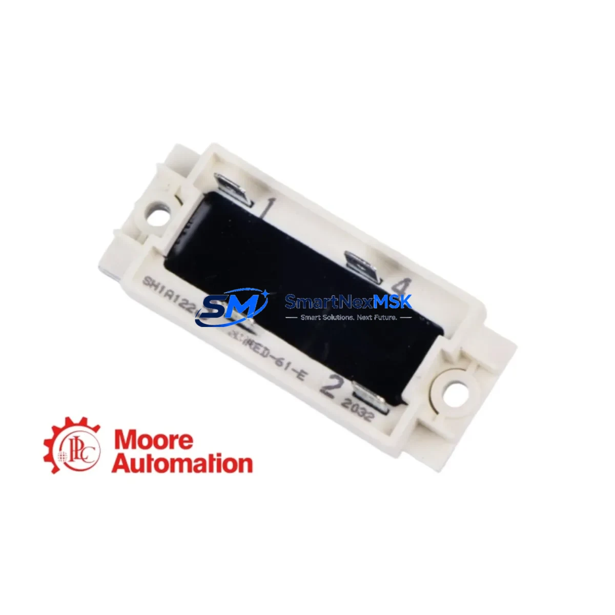
ABB NRED-61-E Retrofit-Ready Output Relay Module for ACS800/ACS880 Control Systems
The ABB NRED-61-E is a relay output extension module engineered for ABB’s ACS800 and ACS880 series variable frequency drives. Designed as a direct retrofit-ready replacement for aging or discontinued relay output configurations, the NRED-61-E provides six independent relay outputs that expand the digital I/O capacity of existing drive systems without requiring a full control platform overhaul. For facilities managing legacy ACS800 installations or transitioning to the ACS880 platform, this module represents a cost-effective, low-disruption path to restoring or upgrading relay-based control logic.
Industrial sites running continuous processes — including paper mills, water treatment plants, compressor stations, and conveyor systems — frequently encounter the challenge of sourcing discontinued relay output boards. The NRED-61-E addresses this directly: it is compatible with the RDCO-02 and RDCO-04 communication adapter boards commonly found in ACS800 cabinets, and integrates cleanly with the RMIO-11C and RMIO-02C main control boards. When replacing an older relay module, engineers should verify the terminal block pitch, confirm the relay contact rating (250 VAC / 30 VDC, 6 A resistive), and cross-reference the module address assignment in the drive’s parameter group 14 (Relay Outputs) to ensure the replacement maps correctly to the existing PLC logic.
For ACS880 retrofit projects, the NRED-61-E connects via the drive’s I/O extension slot and is recognized by the ACS880’s primary control unit (BCU-12 or BCU-22) without firmware modification in most standard configurations. Engineers migrating from ACS800 to ACS880 should note that the parameter mapping for relay outputs shifts from group 14 to the ACS880’s parameter group 10 (Standard DI, RO), requiring a controlled parameter migration session using Drive Composer Pro or DriveWindow Light 2 before live commissioning.
Upgrade Compatibility Table
| Attribute | Detail |
|---|---|
| Compatible Drive Series | ABB ACS800, ACS880 |
| Relay Outputs | 6 × relay outputs (250 VAC / 30 VDC, 6 A resistive) |
| Interface / Backplane | I/O extension slot; compatible with RMIO-11C, RMIO-02C, BCU-12, BCU-22 |
| Communication Compatibility | RDCO-02, RDCO-04 (DDCS); Modbus RTU via RMBA-01 adapter |
| Installation Requirement | Drive must be powered down; ESD precautions required; slot alignment per ACS800/ACS880 hardware manual |
| Parameter Commissioning | ACS800: Group 14 (Relay Outputs); ACS880: Group 10 (Standard DI, RO) |
| Replacement Recommendation | Direct drop-in for NRED-61-E; verify terminal wiring and relay address before restart |
| Commissioning Tools | Drive Composer Pro, DriveWindow Light 2, CDP control panel |
| Warranty | 12-Month Warranty — covers manufacturing defects and functional failure under normal operating conditions |
Retrofit Planning for Existing Automation Systems
A successful NRED-61-E retrofit begins well before the module arrives on site. The first step is a full audit of the existing control cabinet: document the current relay output wiring from the terminal block to the field devices — motor contactors, solenoid valves, alarm annunciators, and safety interlocks. Photograph the existing NRED-61-E or equivalent relay board before removal, noting the terminal numbers and wire labels.
In multi-drive ACS800 installations, the NRED-61-E often works alongside the NDIO-01 digital I/O extension module and the NAMC-11 or NAMC-03 application control boards. If the cabinet also includes an NPBA-12 PROFIBUS adapter or an NMBP-01 Modbus Plus module for fieldbus communication, confirm that the relay output assignments referenced in the PLC program (typically a Siemens S7-300, S7-400, or Allen-Bradley ControlLogix) still align with the new module’s parameter configuration after replacement.
For ACS880 systems, the NRED-61-E slots into the drive’s option module bay alongside components such as the FENA-21 Ethernet adapter (EtherNet/IP / PROFINET), the FDNA-01 DeviceNet adapter, or the FSCA-01 CANopen adapter. If the site uses an ABB AC500 PLC or a third-party SCADA system communicating over PROFINET, verify that the relay output status words are correctly mapped in the fieldbus configuration tool before re-energizing the drive.
HMI screens — whether running on an ABB CP600 panel, a Siemens TP700 Comfort, or a Weintek cMT series — typically display relay output states as discrete bit values. After module replacement, perform a forced-output test from the HMI or PLC to confirm each relay energizes and de-energizes correctly before returning the system to automatic mode. Also verify that the DDCS fiber-optic link (if present, using RDCO-04) is intact and that the drive’s fault log is clear before final sign-off.
Downtime Control During System Migration
Minimizing unplanned downtime during an NRED-61-E replacement requires a structured pre-outage checklist. Before the scheduled maintenance window, back up the full drive parameter set using Drive Composer Pro or a CDP control panel memory card — this preserves all relay output assignments, scaling values, and interlock logic. If the ACS800 is part of a master-follower configuration using DDCS, document the follower address and communication cycle time to restore the link correctly after module swap.
During the outage, follow the ACS800 or ACS880 hardware manual’s lockout/tagout procedure, discharge the DC bus fully (minimum 5 minutes after power-off), and use an ESD wrist strap when handling the NRED-61-E. Slot the replacement module firmly until the retention latch clicks. Re-terminate all relay output wires to the same terminal positions as documented in the pre-outage audit.
On power-up, navigate to the relay output parameter group and verify each output assignment before enabling the drive. Run a controlled test cycle — jog mode or a low-speed ramp — while monitoring relay status on the HMI. Confirm that all downstream field devices (contactors, valves, alarms) respond correctly. A typical NRED-61-E swap, when pre-planned, can be completed within a 2–4 hour maintenance window, keeping production impact to a minimum.
Retrofit Support FAQ
Q1: Is the NRED-61-E a direct drop-in replacement for the original module in my ACS800?
Yes. The NRED-61-E is the standard ABB relay output extension module for the ACS800 and ACS880 series. It uses the same I/O extension slot and terminal block layout as the original. After installation, verify relay output parameter assignments in group 14 (ACS800) or group 10 (ACS880) to confirm the replacement maps to your existing PLC logic without modification.
Q2: Do I need to re-commission the drive after replacing the NRED-61-E?
A full re-commissioning is not required if the parameter backup was saved before removal. Restore the parameter set via Drive Composer Pro or the CDP panel, then perform a relay output forced-test to verify each output operates correctly. If no backup exists, manually re-enter the relay output assignments from your documented wiring records.
Q3: What wiring checks are critical before powering up after module replacement?
Confirm that all relay output terminals are re-terminated to the correct positions, that no wires are crossed between NO (normally open) and NC (normally closed) contacts, and that the relay contact voltage and current ratings of your field devices do not exceed 250 VAC / 6 A resistive. Also verify that the module is fully seated in the backplane slot before applying power.
Q4: What does the 12-month warranty cover?
The 12-month warranty covers manufacturing defects and functional failure under normal operating conditions from the date of shipment. Each unit undergoes pre-shipment functional testing. Warranty claims are supported by SMARTNEXMSK’s technical team — contact [email protected] with your order number and a description of the fault for rapid resolution.
© 2026 SMARTNEXMSK. All rights reserved.
Original Source: https://smartnexmsk.com
Contact: [email protected] | +86 18259474341



