
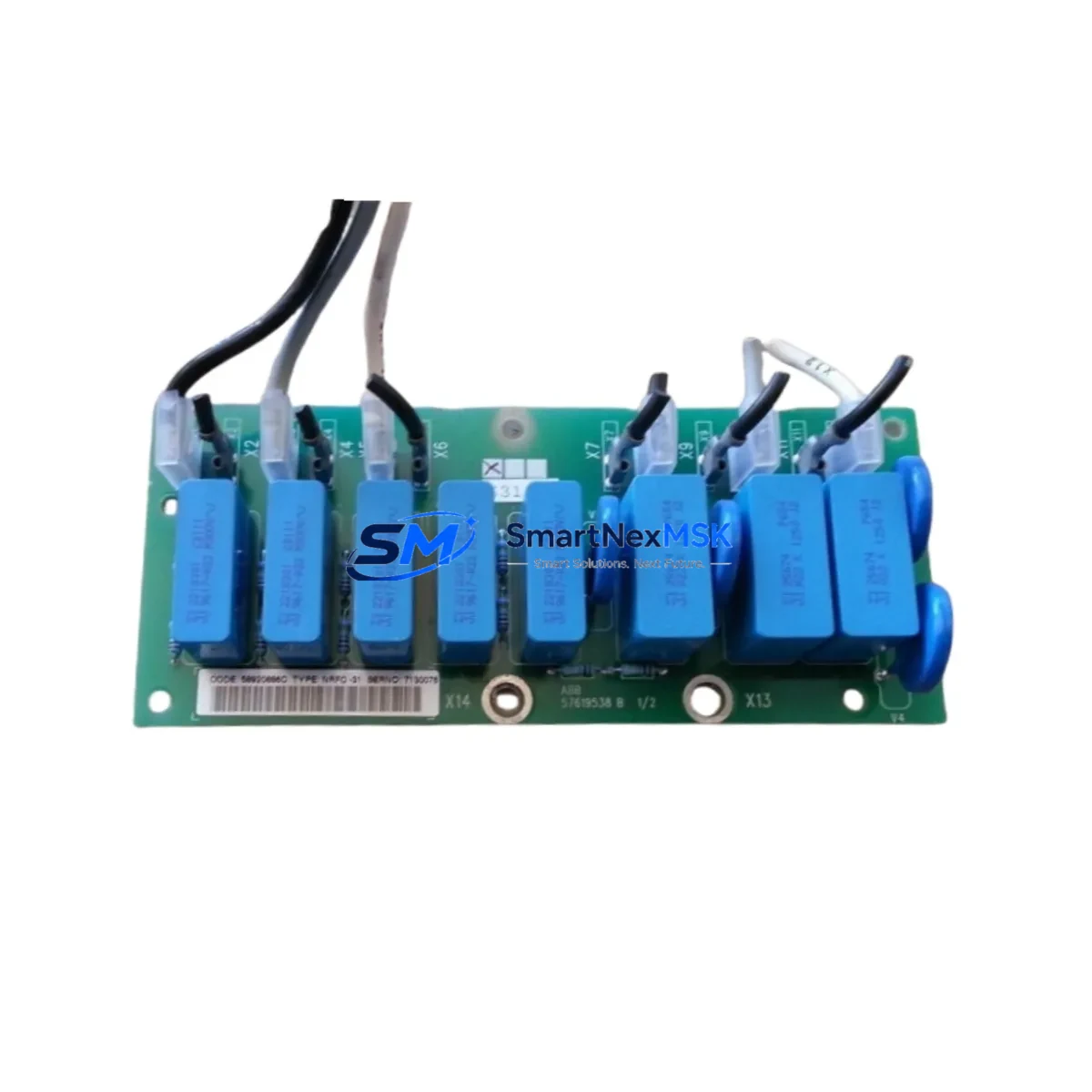
ABB NRFC-31 Maintenance-Ready Spare for AC500 Automation
The ABB NRFC-31 is a fieldbus communication module designed for the AC500 PLC platform — one of ABB’s most widely deployed industrial automation series across process, manufacturing, and infrastructure applications. For maintenance engineers managing aging control systems or executing planned overhauls, having a verified, original NRFC-31 spare on hand is a critical element of any downtime-reduction strategy. Unplanned fieldbus communication failures can cascade rapidly: a single failed module can isolate entire I/O segments, disrupt PROFIBUS or DeviceNet networks, and halt production lines within minutes. Sourcing a tested, original replacement unit in advance is the most effective way to contain that risk.
At SMARTNEXMSK, every NRFC-31 unit is sourced from authorized supply chains, inspected against ABB’s original specifications, and tested for communication integrity before shipment. Each unit ships with a 12-month warranty and full documentation support, making it suitable for both emergency replacement and planned spare parts inventory programs.
Spare Maintenance Table
| Parameter | Specification |
|---|---|
| SKU / Part Number | NRFC-31 |
| Brand | ABB |
| Series | AC500 |
| Module Type | Fieldbus Communication Module |
| Supported Protocols | PROFIBUS DP, DeviceNet (series-dependent slot) |
| Mounting | AC500 CPU/expansion backplane slot |
| Supply Voltage | Supplied via backplane (no external power required) |
| Operating Temperature | 0°C to +60°C |
| Storage Temperature | -25°C to +70°C |
| Protection Rating | IP20 (panel-mounted) |
| Country of Origin | Germany (DE) |
| Compatibility | ABB AC500 PM5xx / PM5xx-ETH CPU families |
| Installation | Hot-swap capable per AC500 system rules; verify CPU firmware version |
| Application Environment | Industrial control panels, process automation, machine control |
| Maintenance Recommendation | Inspect bus termination resistors and cable shielding at each replacement |
| Warranty | 12 Months — tested before shipment |
Maintenance Planning for Continuous Operation
When a fieldbus communication fault is traced to the NRFC-31 module, experienced maintenance engineers know that the module itself is rarely the only component that warrants attention. A thorough site inspection during the replacement window should cover the full communication chain and adjacent power infrastructure.
Begin with the AC500 CPU module (PM564, PM573, or PM583 series, depending on your installation) — verify firmware version compatibility with the replacement NRFC-31 and check for any logged communication errors that predate the fault. Inspect the TB521 or TB541 terminal base on which the NRFC-31 is seated; damaged or corroded contacts on the terminal base are a common secondary cause of intermittent fieldbus faults that survive a module swap.
Check the PS501 or PS502 power supply module supplying the AC500 rack — voltage sag under load is a known trigger for communication module resets. If the installation includes a CM589-PNIO PROFINET I/O coupler or a CI590-CS31-HA CS31 communication interface in the same cabinet, inspect those modules for error LEDs and verify their bus addresses have not shifted.
On the fieldbus cable side, check the PROFIBUS DP bus termination at both ends of the segment — missing or double-terminated segments are a frequent cause of communication instability that gets misdiagnosed as a module failure. Inspect signal isolators on long cable runs and verify that cable shielding is grounded at one end only per ABB’s wiring guidelines.
For installations with distributed I/O, review the status of ABB S500 I/O modules (DI581, DO581, AI531, AO531) connected downstream of the NRFC-31 — a fieldbus reset can leave remote I/O in an undefined state that requires a controlled re-initialization sequence. If the cabinet includes ABB CP600 or CP620 HMI panels, verify that the HMI communication parameters are restored after the module replacement, as some firmware versions require a manual re-link after a fieldbus module change.
Finally, inspect the 24VDC distribution fuses and miniature circuit breakers feeding the control cabinet — a nuisance trip on the control power rail is often the root cause of a fieldbus module fault that appears hardware-related. Keeping a documented spare parts list that includes the NRFC-31 alongside these associated components is the foundation of a robust preventive maintenance program.
Site Replacement Workflow
Step 1 — Pre-replacement documentation: Record the current PROFIBUS node address, baud rate setting, and any DIP switch positions on the existing NRFC-31 before removal. Photograph the module label and wiring for reference.
Step 2 — Safe isolation: Follow your site’s lockout/tagout procedure. The AC500 platform supports controlled CPU stop mode — place the CPU in STOP before removing the communication module to prevent uncontrolled I/O state changes on the fieldbus segment.
Step 3 — Module removal and inspection: Remove the NRFC-31 from its terminal base slot. Inspect the terminal base connector pins for corrosion or mechanical damage. Clean with isopropyl alcohol if required before seating the replacement unit.
Step 4 — Replacement installation: Seat the new NRFC-31 firmly into the terminal base. Confirm the module’s address and baud rate settings match the recorded values. The NRFC-31 is configured via the AC500 programming tool (Automation Builder / PS501 Control Builder Plus) — no hardware DIP switches for address on most variants.
Step 5 — System restart and verification: Return the CPU to RUN mode. Monitor the PROFIBUS diagnostic LEDs on the NRFC-31 — BF (Bus Fault) LED should extinguish within the bus cycle time once all slave devices are recognized. Verify all downstream I/O modules report healthy status in the diagnostic buffer.
Step 6 — Documentation update: Log the replacement in your maintenance management system (CMMS), update the spare parts inventory, and note the firmware version of the replacement module for future reference. This workflow is compatible with legacy AC500 installations and current AC500-S safety-rated systems, ensuring long-term system continuity without requiring a full platform migration.
Spare Parts Support FAQ
Q1: Is the NRFC-31 compatible with all AC500 CPU variants?
The NRFC-31 is designed for the ABB AC500 platform and is compatible with PM5xx series CPUs. Compatibility with specific CPU firmware versions should be verified against ABB’s compatibility matrix. SMARTNEXMSK provides pre-shipment compatibility confirmation upon request — contact us with your CPU part number and firmware version before ordering.
Q2: What testing is performed before shipment?
Every NRFC-31 unit undergoes functional communication testing and visual inspection prior to dispatch. Units are verified for correct module identification, LED diagnostic response, and backplane interface integrity. A test report is available upon request for critical infrastructure applications.
Q3: What does the 12-month warranty cover?
The 12-month warranty covers manufacturing defects and functional failures under normal operating conditions. It does not cover damage resulting from incorrect installation, overvoltage events, or environmental conditions outside the specified operating range. Warranty claims are processed with priority turnaround to minimize your system downtime.
Q4: Can the NRFC-31 replace older or discontinued ABB fieldbus modules in legacy AC500 systems?
In many cases, yes. The NRFC-31 is a current-generation module that can replace earlier fieldbus communication options in AC500 racks, subject to slot compatibility and firmware support. For legacy system life extension projects, SMARTNEXMSK can advise on cross-reference compatibility and supply both current and end-of-life ABB AC500 spare parts to support long-term operational continuity.
© 2026 SMARTNEXMSK. All rights reserved.
Original Source: https://smartnexmsk.com
Contact: [email protected] | +86 18259474341



