
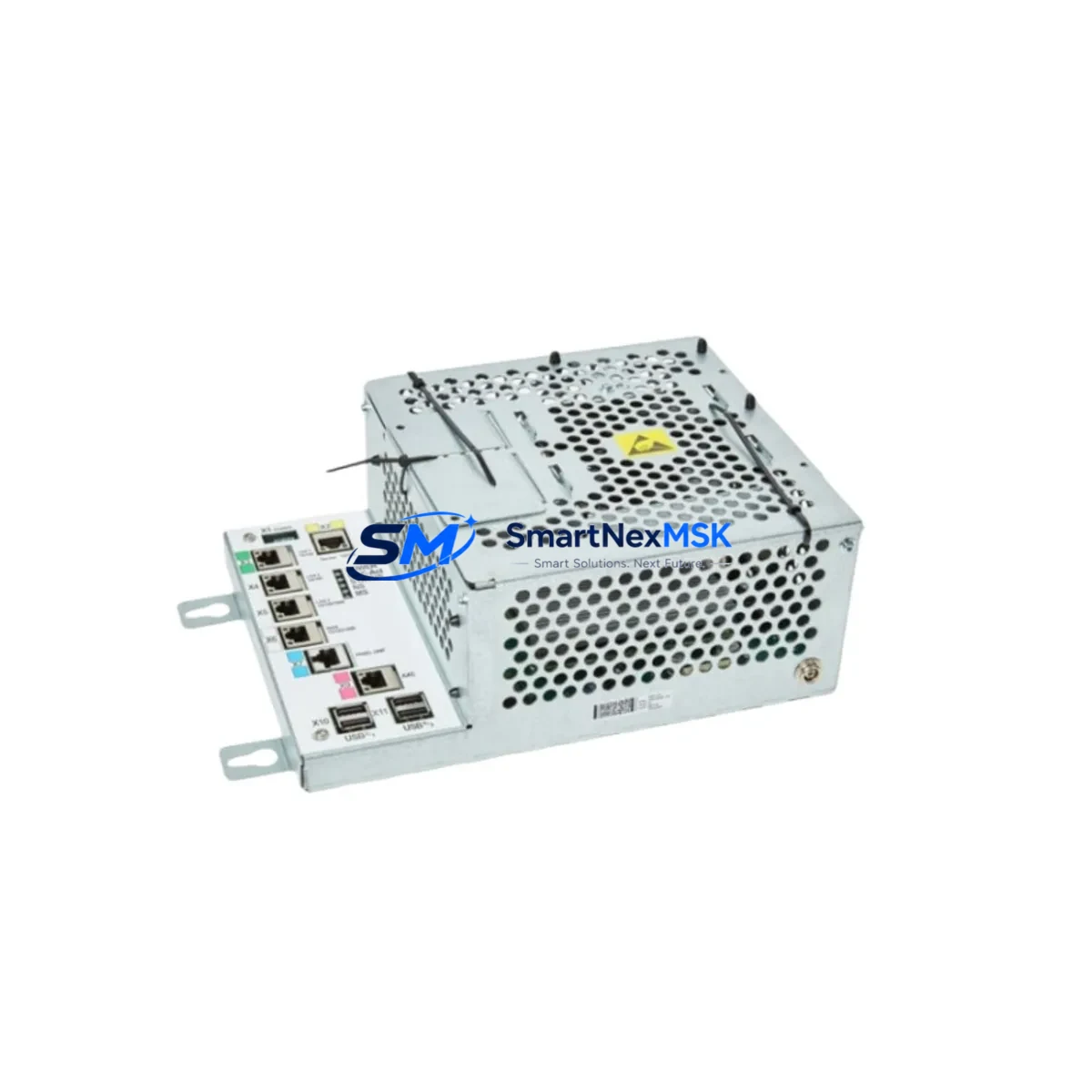
ABB OTCFDCPUL21700CL21700C03UM342B Retrofit-Ready DC PSU for OTC Series Control Systems
The ABB OTCFDCPUL21700CL21700C03UM342B is a DC power supply module engineered for seamless integration into ABB OTC Series control systems. As legacy automation infrastructure ages and original components reach end-of-life, this module serves as a verified retrofit-ready replacement that preserves existing wiring layouts, backplane interfaces, and control logic without requiring a full system overhaul. Whether you are managing a planned upgrade cycle or responding to an unplanned failure on the production floor, the OTCFDCPUL21700CL21700C03UM342B delivers the electrical performance and mechanical compatibility required to restore system operation with minimal disruption.
This module is specifically suited for engineers and maintenance teams working within ABB OTC Series control cabinets where the original DC power supply has been discontinued or is no longer available through standard distribution channels. The unit supports the voltage and current ratings consistent with the OTC platform’s power architecture, making it a direct functional substitute for aging or failed units in the same product family. Before installation, engineers should verify the output voltage specification, terminal block pitch, and backplane connector alignment against the existing installation to confirm a drop-in fit.
Upgrade Compatibility Table
| Parameter | Details |
|---|---|
| Compatible Platform | ABB OTC Series Control Systems |
| Module Function | DC Power Supply |
| Replacement Target | Discontinued OTC Series DC PSU variants |
| Terminal Interface | Compatible with OTC Series terminal block pitch and wiring layout |
| Backplane / Rack Interface | OTC Series standard backplane connector |
| Communication Compatibility | Passive power module; no protocol dependency |
| Installation Requirement | Verify output voltage, current rating, and connector alignment before installation |
| Retrofit Recommendation | Direct replacement; retain original wiring harness where possible |
| Commissioning Focus | Output voltage verification, load test, and thermal check under operating conditions |
| Warranty | 12-Month Warranty — covers manufacturing defects and functional failure under normal operating conditions |
Retrofit Planning for Existing Automation Systems
Successful retrofit of the OTCFDCPUL21700CL21700C03UM342B into an existing OTC Series control cabinet requires a structured pre-installation assessment. Begin by auditing the power distribution architecture within the control cabinet. Identify the total connected load across all installed modules — including the OTC Series CPU module, any installed I/O expansion modules, and communication interface cards — to confirm that the replacement power supply’s rated output current is sufficient for the aggregate demand. Undersized power supply selection is one of the most common causes of intermittent faults and unexpected shutdowns in retrofitted systems.
Next, inspect the existing terminal wiring. The OTC Series uses a defined terminal block layout for DC power distribution, and the replacement module must match the original terminal pitch and polarity markings. Where the original wiring harness is intact and undamaged, it is strongly recommended to retain it in place and connect directly to the replacement module’s terminals, reducing the risk of wiring errors during the changeover. Label all conductors before disconnection if the harness must be disturbed.
The backplane interface is equally critical. The OTCFDCPUL21700CL21700C03UM342B is designed to seat into the OTC Series rack or backplane assembly. Confirm that the rack’s connector pins are clean and undamaged before insertion. In systems where the rack itself has been in service for an extended period, inspect the backplane connector for oxidation or mechanical wear, as a degraded backplane connection can cause intermittent power faults even with a new module installed.
For systems that also include an ABB OTC Series communication module — such as a PROFIBUS DP interface card or an Ethernet-based communication adapter — verify that the power supply changeover does not interrupt the communication link to the host SCADA or DCS system. In many OTC Series installations, the communication module draws its operating power directly from the backplane, meaning a power interruption during module swap will cause a temporary loss of the communication link. Coordinate with the control room operator before proceeding, and confirm that the HMI display associated with the OTC controller is set to show a maintenance status rather than a fault alarm during the swap window.
Where the system includes analog I/O modules or digital I/O expansion cards mounted in the same rack, note that these modules may retain their last output state or default to a safe de-energized state depending on the configured fail-safe behavior. Review the I/O module configuration in the programming software before the swap to understand the expected behavior during the power interruption. If the process requires continuous output during the changeover — for example, in a temperature control loop or a motor drive interlock circuit — plan for a temporary bypass or manual override before removing the failed power supply.
Programming cable access is not required for a power supply replacement in most OTC Series configurations, as the CPU module retains its program in non-volatile memory. However, it is good practice to have a programming cable and a laptop with the appropriate ABB programming environment available on-site during the retrofit, in case a program reload or parameter verification is needed after power restoration. Similarly, ensure that the HMI panel connected to the OTC controller has its project file backed up before the maintenance window begins.
Downtime Control During System Migration
Minimizing production downtime during a power supply retrofit requires advance preparation and a clearly defined changeover sequence. The most effective approach is to schedule the swap during a planned maintenance window rather than responding reactively to a module failure. If the system is already in a failed state, the priority is to restore power as quickly as possible while protecting the integrity of the existing program logic and I/O configuration.
Before removing the failed OTCFDCPUL21700CL21700C03UM342B or its predecessor, document the current state of all output signals and confirm that the CPU module’s program is intact in non-volatile memory. In OTC Series systems, the CPU retains its ladder logic or function block program through a power cycle, so a clean power restoration after the module swap should result in an automatic program resume without requiring a manual reload. However, any retentive data values — such as counters, timers, or recipe parameters stored in retentive memory — should be verified after power restoration to confirm they have been preserved correctly.
The physical swap itself should take no more than a few minutes for a trained technician familiar with the OTC Series rack architecture. Seat the replacement module firmly into the backplane, reconnect the terminal wiring in the correct polarity, and restore power incrementally if the system includes a staged power-up sequence. Monitor the output voltage at the module’s test points before allowing the downstream modules to draw load, and confirm that the voltage is within the specified tolerance before releasing the system back to automatic control.
After power restoration, verify the communication link to the host system, confirm that the HMI display is showing correct process values, and check that all I/O modules are reporting their expected status. A brief functional test of the critical output circuits — particularly any motor starter interlocks, valve actuator commands, or safety relay outputs — should be completed before returning the system to full production operation. Document the replacement with the module serial number, installation date, and post-commissioning test results for maintenance records.
Retrofit Support FAQ
Q: Is the OTCFDCPUL21700CL21700C03UM342B a direct drop-in replacement for the original OTC Series DC power supply?
A: In most OTC Series installations, yes. The module is designed to match the mechanical form factor, terminal layout, and backplane interface of the original OTC Series power supply. However, we recommend verifying the output voltage rating and current capacity against your specific system’s power budget before installation, as some OTC Series variants may have different power requirements depending on the installed I/O and communication modules.
Q: What commissioning steps are required after installing the replacement module?
A: After seating the module and reconnecting the terminal wiring, restore power and verify the output voltage at the module’s test points. Confirm that the CPU module has resumed its program correctly, check that all I/O modules are reporting their expected status, and verify the communication link to the host SCADA or HMI system. A functional test of critical output circuits is recommended before returning the system to automatic operation.
Q: Can the existing wiring harness be reused when installing the OTCFDCPUL21700CL21700C03UM342B?
A: Yes, in most cases the original wiring harness can be retained and connected directly to the replacement module’s terminals, provided the harness is undamaged and the terminal pitch matches. Retaining the original harness reduces the risk of wiring errors and speeds up the changeover process. Inspect all conductors for insulation damage or terminal corrosion before reconnection.
Q: What does the 12-month warranty cover?
A: The 12-month warranty covers manufacturing defects and functional failure under normal operating conditions from the date of shipment. Each unit undergoes pre-shipment functional testing to verify output voltage, load regulation, and connector integrity. Warranty claims are supported by our technical team, and replacement units are dispatched promptly to minimize any impact on your production schedule. Contact [email protected] for warranty service inquiries.
© 2026 SMARTNEXMSK. All rights reserved.
Original Source: https://smartnexmsk.com
Contact: [email protected] | +86 18259474341



