
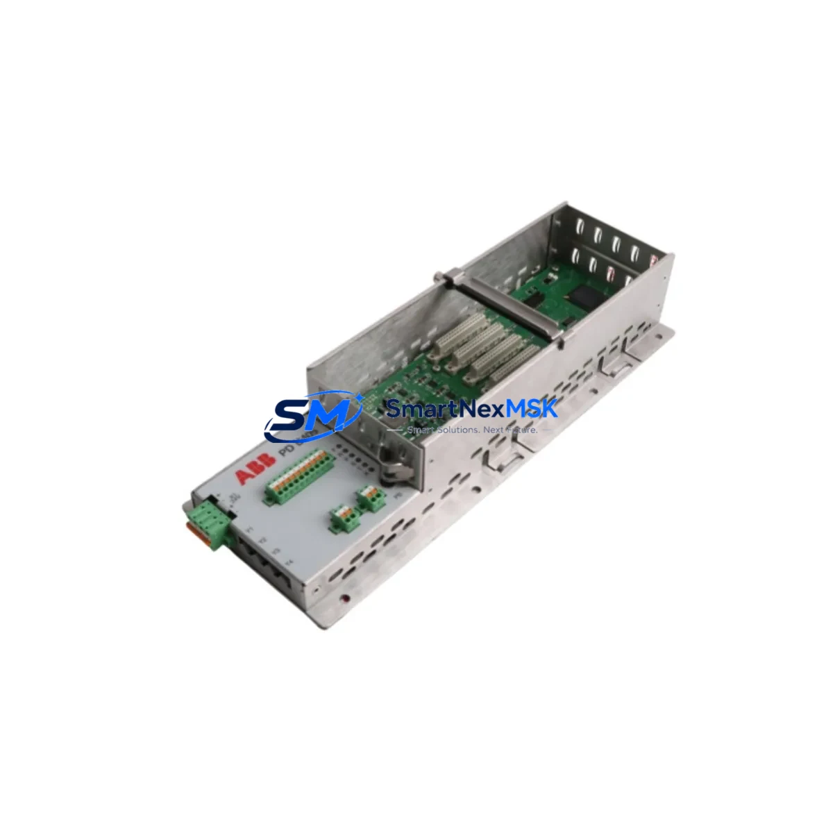
ABB PDD405A101 3BHE041626R0101 Retrofit-Ready DCS Module for AC800M: Seamless Compatibility Upgrade for Legacy Control Systems
The ABB PDD405A101 (alternate part number 3BHE041626R0101) is a processor and communication module designed for the ABB AC800M distributed control system platform. As legacy AC800M installations age and original hardware reaches end-of-life, the PDD405A101 has become a critical retrofit component for engineers managing brownfield upgrades, control cabinet modernization, and unplanned spare-part replacements. SMARTNEXMSK maintains verified stock of this module, pre-tested and shipped with a 12-month warranty, to support your system continuity without forcing a full platform migration.
Upgrade Compatibility Table
| Parameter | Details |
|---|---|
| Compatible Platform | ABB AC800M (PM861, PM864, PM866 controller families) |
| Alternate Part Number | 3BHE041626R0101 |
| Module Function | DCS Processor / Communication Interface Module |
| Backplane Interface | AC800M standard module bus; direct slot replacement |
| Communication Compatibility | PROFIBUS DP, Modbus RTU/TCP, IEC 61850, OPC DA/UA (platform-dependent) |
| Installation Requirement | DIN-rail or rack-mount chassis; no hardware modification required for direct swap |
| Replacement Recommendation | Direct drop-in for failed or end-of-life PDD405A101 units; verify firmware revision before commissioning |
| Commissioning Note | Confirm module address assignment, I/O mapping, and HMI tag binding after installation |
| Warranty | 12 months from date of shipment; covers manufacturing defects and functional failure |
| Pre-shipment Testing | Power-on functional test and communication link verification performed before dispatch |
Retrofit Planning for Existing Automation Systems
Replacing the PDD405A101 in an operating AC800M system requires careful pre-work to avoid extended downtime. Before pulling the module, engineers should document the existing rack configuration, including the slot position of the PDD405A101 relative to adjacent I/O modules such as the AI810 analog input module and the DI810 digital input module. These I/O modules remain in place during a processor swap, but their channel assignments and scaling parameters must be verified against the current Control Builder M project file to ensure no address conflicts arise after the replacement module is initialized.
Power supply capacity is a frequent oversight in retrofit projects. The SD821 or SD822 power supply units feeding the AC800M rack must be confirmed to provide adequate current headroom for the replacement PDD405A101, particularly if additional communication modules such as the CI854 PROFIBUS DP interface or the CI857 INSUM communication interface are installed in the same rack. Overloaded power rails are a leading cause of intermittent faults after module swaps and should be measured under full load before the new module is commissioned.
Backplane integrity is equally important. Inspect the rack connector pins for corrosion or mechanical damage before seating the replacement module. The TB820V2 ModuleBus modem, if present in the system, should also be checked for firmware compatibility with the incoming PDD405A101 revision. Mismatched firmware between the processor module and the ModuleBus modem can prevent the system from completing its startup sequence, resulting in a fault state that mimics hardware failure.
For systems that include an HMI layer built on ABB’s 800xA Information Management platform, the engineering team should prepare updated faceplates and tag references before the cutover window. If the replacement module carries a different hardware revision, some 800xA graphic objects may require re-binding to the new module’s OPC server path. Coordinating this with the control room operator in advance reduces the risk of alarm floods during the first minutes of post-swap operation.
Communication link continuity is critical in multi-drop PROFIBUS DP networks. If the PDD405A101 serves as a PROFIBUS master through an attached CI854 interface, the network segment must be terminated correctly after the swap, and the GSD file configuration in the master should be re-validated. Similarly, if the system uses Modbus TCP for SCADA integration, the IP address and gateway settings stored in the replacement module must be configured to match the original before the network is reconnected.
Downtime Control During System Migration
Minimizing downtime during a PDD405A101 replacement begins with a complete backup of the Control Builder M project, including all task configurations, variable declarations, and communication object definitions. This backup should be stored on an offline engineering workstation and verified for integrity before the maintenance window opens. A second backup copy on removable media provides insurance against workstation failure during the cutover.
Where process conditions allow, a hot-standby or redundant controller configuration using a paired PM864 or PM866 controller can maintain field control continuity while the primary module is replaced. In non-redundant systems, the recommended approach is to place the affected control loops in manual mode at the field level, using local control stations or valve positioners, before removing the PDD405A101. This preserves process stability and gives the engineering team a controlled environment for the swap.
After the replacement module is seated and powered, the Control Builder M project should be downloaded in a phased sequence — first verifying communication with all I/O modules before enabling control tasks. Monitoring the system event log during the first 15 minutes of operation allows early detection of any address conflicts, watchdog timeouts, or communication errors that indicate a configuration mismatch. SMARTNEXMSK’s technical team is available to support remote commissioning guidance for customers who require assistance during this phase.
All modules supplied by SMARTNEXMSK are covered by a 12-month warranty from the date of shipment. Each unit undergoes a power-on functional test and communication verification before dispatch, reducing the risk of receiving a non-functional module during a time-critical maintenance window.
Retrofit Support FAQ
Q: Is the PDD405A101 a direct replacement for my existing unit without any hardware modification?
A: In most AC800M rack configurations, the PDD405A101 is a direct slot-for-slot replacement. No hardware modification to the rack or adjacent modules is required. However, you should verify that the firmware revision of the replacement module is compatible with your Control Builder M project version before commissioning. If a firmware update is needed, this can typically be performed via the engineering workstation before the module is installed in the rack.
Q: What wiring and terminal changes are needed when replacing the PDD405A101?
A: The PDD405A101 itself does not have field wiring terminals — it is a processor and communication module that connects via the backplane. Field wiring to I/O modules such as the AI810 or DI810 remains undisturbed during the swap. The only external connections to verify are communication cables (PROFIBUS, Ethernet, or serial) attached to the module’s front-panel ports, which should be reconnected to the same ports on the replacement unit.
Q: How do I confirm compatibility before ordering?
A: Provide your existing module’s full part number (PDD405A101 or 3BHE041626R0101), the AC800M controller type (PM861, PM864, or PM866), and your Control Builder M software version. SMARTNEXMSK’s technical team will confirm compatibility and advise on any firmware considerations before shipment. Contact us at [email protected] or +86 18259474341.
Q: What does the 12-month warranty cover, and what is the claims process?
A: The 12-month warranty covers manufacturing defects and functional failure under normal operating conditions. If a module fails within the warranty period, contact SMARTNEXMSK with your order reference and a description of the fault. We will arrange a replacement or repair at no additional cost. Pre-shipment testing documentation is available upon request to support your incoming inspection process.
© 2026 SMARTNEXMSK. All rights reserved.
Original Source: https://smartnexmsk.com
Contact: [email protected] | +86 18259474341



