
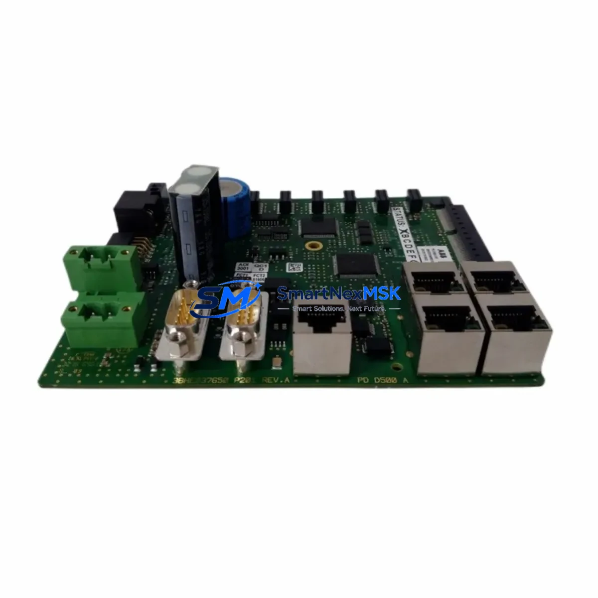
ABB PDD405A101 3BHE041626R0101 Retrofit-Ready Excitation Control for UNITROL Control Systems
The ABB PDD405A101 (catalog reference 3BHE041626R0101) is a precision excitation control module engineered for the ABB UNITROL series of automatic voltage regulators (AVRs) and generator excitation systems. As legacy UNITROL 1000, UNITROL 5000, and UNITROL 6000 installations approach end-of-service milestones, plant engineers and system integrators increasingly rely on the PDD405A101 as a verified, drop-in compatible replacement that preserves existing control logic, wiring infrastructure, and communication architecture without requiring a full system overhaul.
This module serves as the pulse distribution and drive interface within the UNITROL excitation chain, coordinating firing pulse signals to the thyristor bridge and maintaining synchronization with the generator’s field winding. When the original PDD405A101 fails or becomes unavailable through standard OEM channels, sourcing a tested replacement is critical to restoring generator excitation control and avoiding extended unplanned outages at power stations, industrial co-generation plants, and large motor-drive installations.
Upgrade Compatibility Table
| Parameter | Details |
|---|---|
| Compatible Series | ABB UNITROL 1000, UNITROL 5000, UNITROL 6000 |
| Part Number | PDD405A101 / 3BHE041626R0101 |
| Module Function | Pulse Distribution & Drive, Excitation Control |
| Backplane Interface | UNITROL standard rack bus connector |
| Communication Compatibility | PROFIBUS-DP, LON, internal UNITROL bus |
| Installation Requirement | Direct slot replacement; verify rack address DIP settings |
| Replacement Recommendation | Confirm firmware revision matches host controller |
| Commissioning Focus | Thyristor firing angle calibration, field current loop tuning |
| Warranty | 12 Months |
| Origin | Sweden (ABB) |
Retrofit Planning for Existing Automation Systems
A successful PDD405A101 retrofit begins well before the module arrives on site. Engineers should first audit the existing UNITROL rack assembly to confirm available slot positions, backplane bus integrity, and the revision level of the host AVR controller board — typically the UNITROL AMC or UNITROL REF615 interface card. The rack’s power supply module, such as the UNITROL PSM or an equivalent 24 VDC rail unit, must be verified to deliver sufficient current capacity for the replacement module under full excitation load.
Terminal wiring to the thyristor firing board should be documented before removal. The PDD405A101 interfaces with the thyristor bridge through a dedicated pulse cable harness; technicians should inspect connector pins for oxidation and replace the harness if continuity tests show resistance above specification. Where the original installation used a UNITROL SDCS-CON-4 or SDCS-PIN-48 interface board in an adjacent slot, those boards should remain undisturbed during the swap to preserve the firing synchronization reference.
Communication link integrity is equally important. Sites running PROFIBUS-DP networks connecting the UNITROL system to a DCS or SCADA platform — for example, an ABB Symphony Plus or ABB 800xA distributed control system — should verify that the PROFIBUS node address assigned to the excitation controller is correctly re-entered after module replacement. LON-based installations require re-binding of the network variable connections using the UNITROL commissioning tool before returning the generator to service.
For sites migrating from older UNITROL 1000 hardware to UNITROL 5000 or 6000 architecture, the PDD405A101 is a key transitional component. The upgrade path typically involves retaining the existing excitation transformer and thyristor bridge while replacing the control electronics rack. In this scenario, the UNITROL AMC controller, the PDD405A101 pulse distribution module, and the UNITROL measurement board are replaced as a coordinated set, with the field flashing circuit and manual control backup verified independently before the first auto-excitation test.
I/O mapping should be reviewed against the original generator protection relay — commonly an ABB REG216 or REX521 — to confirm that the field current feedback signal, the excitation on/off interlock, and the AVR auto/manual transfer signal are correctly wired to the new module’s terminal block. Any discrepancy in signal polarity or scaling will cause instability during the initial field current ramp-up and must be corrected before synchronizing the generator to the grid.
Downtime Control During System Migration
Minimizing outage duration during a PDD405A101 replacement requires a structured pre-outage preparation protocol. Before taking the generator offline, technicians should export the full UNITROL parameter set using the UNITROL commissioning software and store a backup on an isolated engineering laptop. This parameter file captures all PI controller gains, field current limits, reactive power droop settings, and protection thresholds, and can be reloaded to the replacement module within minutes of installation.
Where a hot-standby excitation channel is available — as in dual-channel UNITROL 6000 configurations — the transfer to the standby channel should be executed first, allowing the faulty PDD405A101 to be replaced while the generator remains online. Single-channel sites must coordinate the outage window with the grid operator and ensure that the manual field rheostat or the static excitation backup is available to maintain field current during the transition if required by site safety procedures.
After physical installation, the commissioning sequence should follow the UNITROL startup checklist: verify DC bus voltage, confirm pulse output signals on the oscilloscope before enabling the thyristor bridge, perform a no-load field current ramp test, and validate the AVR voltage regulation response before connecting to the busbar. This structured approach consistently achieves return-to-service within a planned four-to-eight-hour maintenance window, even on first-time replacements.
Retrofit Support FAQ
Q: Is the PDD405A101 a direct replacement for the original 3BHE041626R0101 without firmware changes?
A: In most UNITROL 5000 and 6000 installations, the PDD405A101 is a direct hardware replacement. However, if the host AMC controller firmware is below a certain revision, a firmware update may be required to ensure full compatibility with the replacement module’s pulse interface protocol. We recommend confirming the AMC firmware version before ordering.
Q: What wiring checks are mandatory before powering up the replacement module?
A: Verify the pulse cable harness continuity, confirm the rack backplane connector seating, check the 24 VDC supply rail voltage at the module slot, and ensure all thyristor gate connections are secure. Do not energize the thyristor bridge until pulse output signals have been confirmed on a calibrated oscilloscope.
Q: Can this module be used in a UNITROL 1000 system?
A: The PDD405A101 is primarily specified for UNITROL 5000 and 6000 platforms. Use in a UNITROL 1000 rack requires verification of backplane bus compatibility and may require an adapter bracket. Contact our technical team with your rack serial number for a definitive compatibility assessment.
Q: What does the 12-month warranty cover?
A: Our 12-month warranty covers manufacturing defects and functional failures under normal operating conditions. Each unit undergoes pre-shipment functional testing on a UNITROL-compatible test bench. The warranty does not cover damage resulting from incorrect installation, overvoltage events, or operation outside the module’s rated environmental specifications.
© 2026 SMARTNEXMSK. All rights reserved.
Original Source: https://smartnexmsk.com
Contact: [email protected] | +86 18259474341



