
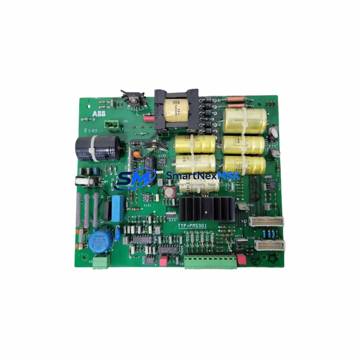
ABB PM5301 Retrofit-Ready Drive Control Board for ACS880 Control Systems
The ABB PM5301 is a high-performance drive control board engineered for seamless compatibility with the ACS880 series of industrial AC drives. Designed to serve as a direct retrofit replacement for aging or discontinued control modules, the PM5301 enables plant engineers and system integrators to modernize legacy automation infrastructure without requiring full drive replacement or extensive reprogramming. Whether you are managing a planned upgrade cycle or responding to an unplanned failure on a critical production line, the PM5301 delivers the electrical compatibility, communication protocol support, and mechanical fit required for a confident, low-downtime swap.
At SMARTNEXMSK, we maintain verified stock of the PM5301 and ship globally with full pre-shipment functional testing and a 12-month warranty covering both parts and workmanship. Every unit is inspected against ABB factory specifications before dispatch.
Upgrade Compatibility Table
| Parameter | Details |
|---|---|
| Compatible Drive Series | ABB ACS880 (all frame sizes) |
| Replaces / Supersedes | PM5301, legacy ACS800 control boards (with adapter) |
| Mounting Interface | Standard ACS880 control unit slot; DIN rail compatible |
| Communication Protocols | PROFIBUS-DP, Modbus RTU, EtherNet/IP, DDCS fiber |
| I/O Compatibility | Compatible with RDIO-01, RAIO-01, and RDNA-01 extension modules |
| Power Supply Requirement | 24 VDC ± 10%, internal SMPS from drive bus |
| Firmware Compatibility | Supports ACS880 firmware v2.x and above; parameter backup recommended |
| Installation Requirement | Parameter restore via Drive Composer or Panel PC; no hardware modification |
| Commissioning Tool | ABB Drive Composer Pro / Assistant Control Panel ACS-AP-I |
| Retrofit Recommendation | Direct replacement; verify macro selection and application program version |
| Debugging Focus | Speed reference scaling, fieldbus node address, I/O mapping, fault history reset |
| Warranty | 12 Months — Parts & Workmanship |
Retrofit Planning for Existing Automation Systems
Successful PM5301 retrofits begin well before the physical swap. During the planning phase, engineers should export the full parameter set from the existing control board using Drive Composer Pro or the ACS-AP-I assistant panel. This backup preserves motor data, application macros, PID tuning values, and fieldbus configuration — all of which must be restored to the replacement PM5301 after installation.
In systems where the ACS880 drive communicates over PROFIBUS-DP via an RPBA-01 adapter module, the node address and baud rate settings stored in the outgoing control board must be documented and re-entered manually, as these are not always captured in a standard parameter backup. Similarly, if the drive is integrated into a DDCS fiber ring connecting to an ABB AC800M controller or a Symphony Plus DCS, the fiber port assignments and node IDs must be verified against the network topology diagram before the new PM5301 is brought online.
For installations using RDIO-01 digital I/O extension modules or RAIO-01 analog I/O modules mounted on the drive’s option slot, confirm that the extension module firmware is compatible with the PM5301 control board version. Incompatible firmware combinations can cause I/O mapping errors that are difficult to diagnose under time pressure during a production restart.
Power supply capacity is a frequently overlooked retrofit variable. The PM5301 draws its 24 VDC logic supply from the drive’s internal SMPS, but in older ACS880 frames where the power supply board has degraded, the available current margin may be insufficient to support both the new control board and any connected option modules simultaneously. Before installation, measure the 24 VDC rail under load and compare against the PM5301’s specified current draw. If the margin is less than 15%, consider replacing the AINT-02 or AINT-11 power interface board as part of the same maintenance window.
In control cabinets where the ACS880 is paired with an ACS-AP-W wall-mounted panel or a remote keypad connected via an OPMP-01 panel bus cable, verify that the panel communication link is re-established after the PM5301 swap. Panel bus faults are a common post-retrofit issue that can prevent operators from acknowledging drive faults or adjusting speed references from the HMI station.
For sites running ABB Ability™ Drive Manager or integrating drive data into a SCADA system via OPC-UA, the PM5301’s Ethernet port configuration — including IP address, subnet mask, and gateway — must be reconfigured after installation. Document these settings from the outgoing board before removal. If the drive is connected to a Modbus RTU network alongside other field devices such as soft starters, motor protection relays, or remote I/O stations, confirm that the PM5301’s Modbus slave address does not conflict with any existing device on the RS-485 bus.
Downtime Control During System Migration
Minimizing unplanned downtime during a PM5301 swap requires a structured pre-work checklist completed during a scheduled maintenance window or planned production break. The most effective approach is to treat the control board replacement as a hot-standby swap: have the replacement PM5301 pre-configured with the correct parameter set, macro selection, and fieldbus address before the production line is stopped.
Begin by placing the drive in local control mode and ramping the motor to a controlled stop. Do not remove power until the DC bus voltage has discharged below 50 VDC — verify this with a calibrated multimeter at the DC bus terminals, not by relying on the drive’s internal voltage display, which requires the control board to be functional. Once the bus is discharged, remove the control unit by releasing the two captive screws on the front of the ACS880 control unit housing and sliding the PM5301 out of the backplane connector.
Insert the replacement PM5301, restore the parameter backup, and verify the following before returning the drive to automatic control: motor nameplate data (rated voltage, current, frequency, speed, power), application macro selection, speed reference source and scaling, fieldbus communication status (check parameter group 50 for PROFIBUS or group 58 for Modbus), I/O signal mapping, and fault history. Clear the fault log only after confirming that all pre-existing faults have been reviewed and addressed.
For critical processes where even a brief interruption is unacceptable, consider deploying a bypass contactor arrangement that allows the motor to run across-the-line at fixed speed while the drive control board is being replaced. This approach is particularly effective in HVAC, pump, and fan applications where variable speed control can be temporarily suspended without process impact. Coordinate with the process control team and update the HMI graphic to reflect the bypass status so that operators are not alarmed by the change in drive status indication.
Retrofit Support FAQ
Q1: Is the PM5301 a direct drop-in replacement for the original ACS880 control board, or are hardware modifications required?
The PM5301 is designed as a direct mechanical and electrical replacement for the standard ACS880 control unit slot. No hardware modifications to the drive frame, backplane, or wiring are required. After physical installation, a parameter restore from backup is necessary to return the drive to its previous operating configuration. If the original control board failed before a backup could be taken, SMARTNEXMSK can provide a factory-default parameter template for common ACS880 application macros as a starting point for recommissioning.
Q2: What commissioning steps are required after installing the PM5301?
After installation, connect Drive Composer Pro or the ACS-AP-I assistant panel to the PM5301’s USB or panel bus port. Restore the parameter backup, verify motor nameplate data in parameter group 99, confirm the application macro in parameter 96.04, check fieldbus communication status, and run a motor identification (ID run) if the motor data has changed or if the original ID run data was not captured in the backup. Test all digital and analog I/O signals before returning the drive to automatic control.
Q3: How do I verify wiring compatibility between the PM5301 and my existing terminal block layout?
The PM5301 uses the standard ACS880 control unit terminal layout (X1 through X6 connectors). Compare your existing wiring diagram against the ACS880 hardware manual (3AUA0000085967) to confirm terminal assignments. Pay particular attention to the safe torque off (STO) circuit wiring on terminals X6:1 and X6:2 — incorrect STO wiring will prevent the drive from enabling and may trigger a safety fault that requires a qualified safety engineer to clear.
Q4: What does the 12-month warranty cover, and what is the claims process?
The 12-month warranty covers manufacturing defects, component failures, and workmanship issues under normal operating conditions. It does not cover damage caused by incorrect installation, overvoltage events, environmental contamination, or unauthorized modification. To initiate a warranty claim, contact SMARTNEXMSK at [email protected] with the order number, unit serial number, and a description of the fault symptom. We will arrange return shipping and provide a replacement or repaired unit within the agreed lead time.
© 2026 SMARTNEXMSK. All rights reserved.
Original Source: https://smartnexmsk.com
Contact: [email protected] | +86 18259474341



