
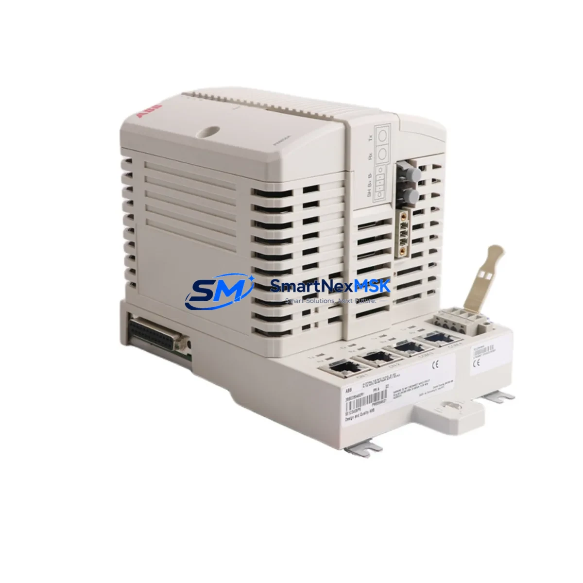
ABB PM856AK01 3BSE066490R1 Retrofit-Ready CPU for AC 800M Control Systems
The ABB PM856AK01 (catalog reference 3BSE066490R1) is a high-performance CPU module engineered for the AC 800M distributed control platform. As legacy AC 800M installations approach end-of-support milestones, plant engineers and system integrators increasingly rely on the PM856AK01 as the primary retrofit solution for aging PM856, PM864, and PM864AK01 processors. This module delivers a seamless upgrade path that preserves existing backplane wiring, retains PROFIBUS DP and Ethernet TCP/IP communication links, and maintains full compatibility with Control Builder M application programs — dramatically reducing the engineering effort and downtime risk associated with a mid-life control system modernization.
Sourced directly from authorized distribution channels and subject to full functional testing prior to shipment, every PM856AK01 unit supplied by SMARTNEXMSK is backed by a 12-month warranty covering manufacturing defects and operational failures under normal industrial service conditions. Units are held in climate-controlled inventory and dispatched with original ABB packaging, factory labels, and a certificate of conformity to support your incoming inspection and asset-management records.
Upgrade Compatibility Table
| Parameter | Legacy Module | PM856AK01 (3BSE066490R1) | Retrofit Note |
|---|---|---|---|
| Replaces | PM856, PM864, PM864AK01 | PM856AK01 | Direct slot-for-slot replacement on TB840 / TB840A backplane |
| Backplane Interface | ModuleBus (TB840 / TB840A) | ModuleBus (TB840 / TB840A) | No backplane hardware change required |
| Communication Ports | PROFIBUS DP, Ethernet | PROFIBUS DP, Ethernet TCP/IP | Retain existing cable routing; verify IP address assignment |
| Power Supply Compatibility | SD821 / SD822 / SD823 | SD821 / SD822 / SD823 | Confirm PSU output capacity ≥ system load after module swap |
| Application Program | Control Builder M project | Control Builder M (v5.1+) | Re-download program after hardware replacement; verify task cycle times |
| I/O Expansion | S800 I/O via CI854 / CI858 | S800 I/O via CI854 / CI858 | No I/O reconfiguration required if module addresses unchanged |
| HMI Connectivity | 800xA / Operate IT | 800xA / Operate IT | Update OPC server node reference if CPU IP address changes |
| Redundancy Support | Hot-standby pair | Hot-standby pair | Replace one CPU at a time; bumpless switchover supported |
| Installation Standard | DIN rail / panel mount | DIN rail / panel mount | Identical mechanical footprint; no cabinet modification needed |
| Warranty | — | 12 Months | Covers manufacturing defects under normal operating conditions |
Retrofit Planning for Existing Automation Systems
A successful PM856AK01 retrofit begins well before the module arrives on site. The first step is a thorough audit of the existing control cabinet: verify that the installed SD822 or SD823 power supply module can sustain the combined current draw of the replacement CPU plus all connected S800 I/O stations. In most AC 800M cabinets, the power budget is adequate, but aging PSUs operating near rated capacity should be load-tested or replaced concurrently with the CPU swap.
Next, document the terminal wiring on the TB840A baseplate. The PM856AK01 uses the same 48-pin ModuleBus connector as its predecessors, so no rewiring is required at the backplane level. However, if the cabinet also houses CI854A PROFIBUS DP communication interface modules or CI858 PROFIBUS DP redundant interface modules, confirm that their firmware versions are compatible with the PM856AK01 CPU firmware to avoid communication initialization errors during commissioning.
For plants running distributed I/O over S800 I/O clusters — including AI810, AO810, DI810, and DO810 signal modules — verify that module addresses configured in the Control Builder M hardware editor match the physical DIP-switch settings on each I/O module. Address mismatches are the most common source of post-retrofit I/O faults and can be identified and corrected before the CPU swap using an offline hardware scan.
If the control system interfaces with an ABB 800xA System or an older Operate IT HMI environment, export and archive all current OPC server configurations and graphic display bindings before beginning the retrofit. After the PM856AK01 is installed and the Control Builder M application is re-downloaded, validate that all HMI tag references resolve correctly and that alarm and event logging resumes without gaps. Where the plant uses TK212A programming cables or USB-to-serial adapters for local CPU access, confirm driver compatibility with the engineering workstation operating system before the maintenance window begins.
Finally, for redundant CPU configurations, coordinate the retrofit sequence with the site control engineer: replace the standby CPU first, allow the system to synchronize, then perform a controlled switchover before replacing the primary unit. This approach eliminates unplanned process interruptions and keeps the control loop active throughout the hardware exchange.
Downtime Control During System Migration
Minimizing production downtime during a CPU retrofit requires a structured pre-outage preparation protocol. Before the maintenance window opens, use Control Builder M to perform a full project backup — including hardware configuration, application code, parameter sets, and communication node definitions. Store this backup on an isolated engineering workstation and a secondary removable medium to guard against data loss during the swap procedure.
During the outage, follow the ABB-recommended CPU replacement sequence: place the AC 800M controller in manual mode, inhibit all output modules to prevent spurious actuator commands, then remove the legacy CPU from the TB840A baseplate. Insert the PM856AK01, allow the module to complete its self-test sequence (indicated by the RUN LED pattern), and re-download the archived application program via Control Builder M. Verify that all I/O modules report healthy status in the hardware editor before releasing outputs from inhibit.
For sites where even brief interruptions are unacceptable, a parallel-run strategy is recommended: install the PM856AK01 in a bench-test rack alongside the existing controller, validate program execution and I/O response against the live system, then perform the physical swap during a scheduled low-production period. This approach compresses the live outage to the time required for a single module exchange and program download — typically under 30 minutes for an experienced technician — and preserves the original program logic without modification.
Retrofit Support FAQ
Q1: Is the PM856AK01 (3BSE066490R1) a direct drop-in replacement for the PM864AK01?
Yes. The PM856AK01 is mechanically and electrically compatible with the TB840 and TB840A baseplates used by the PM864AK01. The module occupies the same slot position, uses the same ModuleBus interface, and supports the same Control Builder M application programs. No backplane rewiring or cabinet modification is required. Confirm firmware version compatibility in Control Builder M before re-downloading the application.
Q2: What commissioning steps are required after installing the PM856AK01?
After physical installation, connect to the CPU via Control Builder M, download the archived application project, and perform a hardware scan to confirm that all I/O modules and communication interfaces — including CI854A PROFIBUS DP modules and S800 I/O stations — are recognized correctly. Verify task cycle times, check alarm and event logs for initialization errors, and confirm HMI tag connectivity before returning the system to automatic control.
Q3: How do I verify wiring and terminal compatibility before the swap?
The PM856AK01 connects to the control cabinet exclusively through the TB840A baseplate ModuleBus connector — there are no field-wiring terminals on the CPU module itself. All field I/O wiring terminates at the S800 I/O module terminal bases, which remain undisturbed during the CPU replacement. Verify that the SD822 or SD823 power supply output voltage and current ratings meet the system load requirements after the new CPU is installed.
Q4: What does the 12-month warranty cover, and what is the return process?
The 12-month warranty covers manufacturing defects and functional failures under normal industrial operating conditions from the date of shipment. Each unit undergoes functional testing prior to dispatch. In the event of a warranty claim, contact SMARTNEXMSK at [email protected] with the order reference and a description of the fault. A replacement unit or repair will be arranged within the agreed service lead time. Physical damage resulting from incorrect installation, overvoltage, or environmental exposure outside the module’s rated operating range is excluded from warranty coverage.
© 2026 SMARTNEXMSK. All rights reserved.
Original Source: https://smartnexmsk.com
Contact: [email protected] | +86 18259474341



