
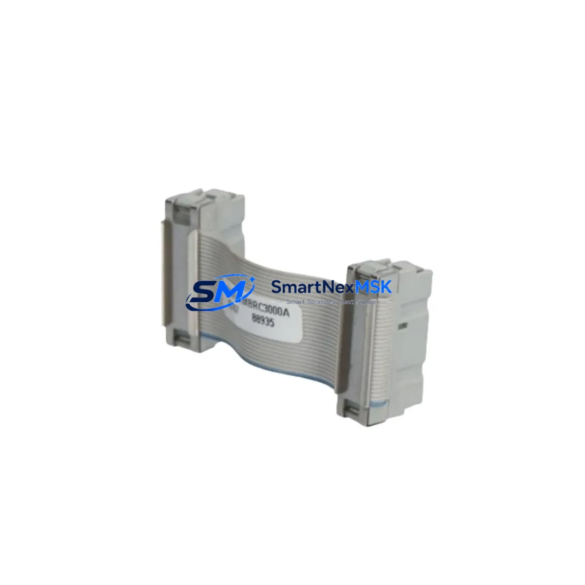
ABB PMKHRMBRC3000A Retrofit-Ready Redundancy Cable for AC500 Control Systems
The ABB PMKHRMBRC3000A is a high-reliability CPU redundancy synchronization cable engineered for the AC500 PLC platform — one of ABB’s most widely deployed modular programmable logic controller families in process automation, power distribution, and industrial manufacturing. As legacy AC500 installations age and original redundancy cables become increasingly difficult to source, the PMKHRMBRC3000A has become a critical retrofit component for engineers tasked with maintaining hot-standby CPU configurations without interrupting production continuity.
This cable provides the dedicated point-to-point synchronization link between the primary and standby CPU modules — typically a pair of PM573, PM583, PM591, or PM595 processors — mounted within the same TB711 or TB721 backplane rack. The synchronization channel carried by the PMKHRMBRC3000A ensures that program state, I/O image data, and communication status are continuously mirrored between the active and redundant CPUs, enabling bumpless switchover in the event of a primary CPU fault. For facilities operating continuous processes where even a brief control interruption carries significant safety or financial risk, maintaining a verified spare PMKHRMBRC3000A in inventory is standard practice.
Upgrade Compatibility Table
| Parameter | Details |
|---|---|
| Compatible CPU Modules | PM573, PM583, PM591, PM595 (AC500 series) |
| Compatible Backplanes / Racks | TB711, TB721 terminal base racks |
| Connector Interface | Dedicated redundancy port on AC500 CPU faceplate (proprietary ABB interface) |
| Installation Requirement | Both CPUs must be powered off or in STOP mode before cable swap; no rack removal required |
| Communication Compatibility | Transparent to PROFIBUS DP, Modbus TCP, EtherNet/IP, and CS31 bus configurations |
| Replacement Recommendation | Direct drop-in replacement; no firmware update or address reconfiguration required |
| Commissioning Focus | Verify redundancy status LED on both CPUs; confirm sync state via Automation Builder diagnostic view |
| Warranty | 12-Month Warranty — covers manufacturing defects and connector integrity |
Retrofit Planning for Existing Automation Systems
When planning a retrofit or cable replacement within an existing AC500 redundant control system, the scope of work extends well beyond the cable itself. Engineers must audit the full control cabinet configuration before scheduling a maintenance window. A typical AC500 redundant installation includes the PM595 CPU pair as the primary controllers, the TB721 rack providing the backplane for both CPUs and associated I/O modules, and a suite of I/O expansion modules such as the DC532 digital input module, DA501 analog output module, and AI531 analog input module. These I/O modules remain fully operational during a cable swap, but their address assignments and I/O image mapping must be documented prior to any intervention to ensure the replacement cable restoration does not trigger unexpected I/O state changes.
Communication infrastructure also requires pre-swap verification. If the system uses a CM589-PNIO PROFINET communication module or a CM572-DP PROFIBUS DP master module, the network topology and device addresses should be captured in the Automation Builder project file before work begins. In installations where the AC500 communicates upstream to a SCADA or DCS via Modbus TCP through the onboard Ethernet port of the PM595, the IP addressing and polling intervals should be noted so that post-swap communication restoration can be validated quickly.
Power supply integrity is another pre-retrofit checkpoint. The PS501 or PS560 power supply modules feeding the rack must be confirmed to be within rated load capacity, particularly if the retrofit is being performed as part of a broader cabinet upgrade that adds new I/O modules or communication cards. Overloaded power supplies are a common root cause of intermittent redundancy sync failures that are misdiagnosed as cable faults.
For sites where the AC500 system interfaces with an ABB CP600 or CP620 HMI panel, the HMI project should be backed up and the communication driver settings verified before and after the cable replacement. HMI screens displaying CPU redundancy status tags should be tested post-commissioning to confirm that the switchover logic is correctly reflected in the operator interface.
Downtime Control During System Migration
Replacing the PMKHRMBRC3000A in a live redundant AC500 system can be accomplished with minimal process disruption when the correct sequence is followed. The recommended approach is to first confirm that the standby CPU is fully synchronized and healthy — this is visible via the redundancy status indicators on both CPU faceplates and through the Automation Builder online diagnostic panel. Once synchronization is confirmed, the primary CPU can be placed in STOP mode, which transfers control authority to the standby CPU without interrupting field I/O or communication links.
With the primary CPU in STOP mode, the PMKHRMBRC3000A can be disconnected and the replacement cable installed. The primary CPU is then returned to RUN mode, at which point the redundancy synchronization process restarts automatically. Full synchronization typically completes within seconds to minutes depending on program size and I/O volume. The entire intervention — from initiating the CPU switchover to confirming restored redundancy — can be completed within a planned maintenance window of under 30 minutes in most AC500 installations, preserving original program logic, retentive data, and communication configurations without modification.
All units supplied are pre-tested for connector continuity and signal integrity prior to shipment. Each PMKHRMBRC3000A is covered by a 12-month warranty against manufacturing defects, ensuring that your retrofit investment is protected from the moment the cable is installed.
Retrofit Support FAQ
Q: Is the PMKHRMBRC3000A a direct replacement for the original ABB redundancy cable in AC500 systems?
A: Yes. The PMKHRMBRC3000A is a direct drop-in replacement compatible with all AC500 CPU modules that support hardware redundancy, including the PM573, PM583, PM591, and PM595. No firmware changes, address reconfiguration, or Automation Builder project modifications are required.
Q: Can the cable be replaced without taking the entire control system offline?
A: In a properly functioning redundant AC500 system, the cable can be replaced by first switching control authority to the standby CPU, then replacing the cable on the primary CPU while the standby maintains field control. Full process shutdown is not required, though a brief CPU switchover event will occur.
Q: What commissioning checks should be performed after installing the replacement cable?
A: After installation, verify that both CPU redundancy status LEDs indicate a synchronized state. Use the Automation Builder online diagnostic view to confirm the redundancy channel is active and that the standby CPU is tracking the primary. Test a manual switchover if the process permits, and confirm that all I/O modules, communication modules, and HMI connections recover correctly after switchover.
Q: What does the 12-month warranty cover?
A: The 12-month warranty covers manufacturing defects including connector integrity, cable continuity, and shielding performance. Units that fail under normal operating conditions within the warranty period will be replaced or refunded. Each unit undergoes pre-shipment testing to verify electrical continuity before dispatch.
© 2026 SMARTNEXMSK. All rights reserved.
Original Source: https://smartnexmsk.com
Contact: [email protected] | +86 18259474341



