
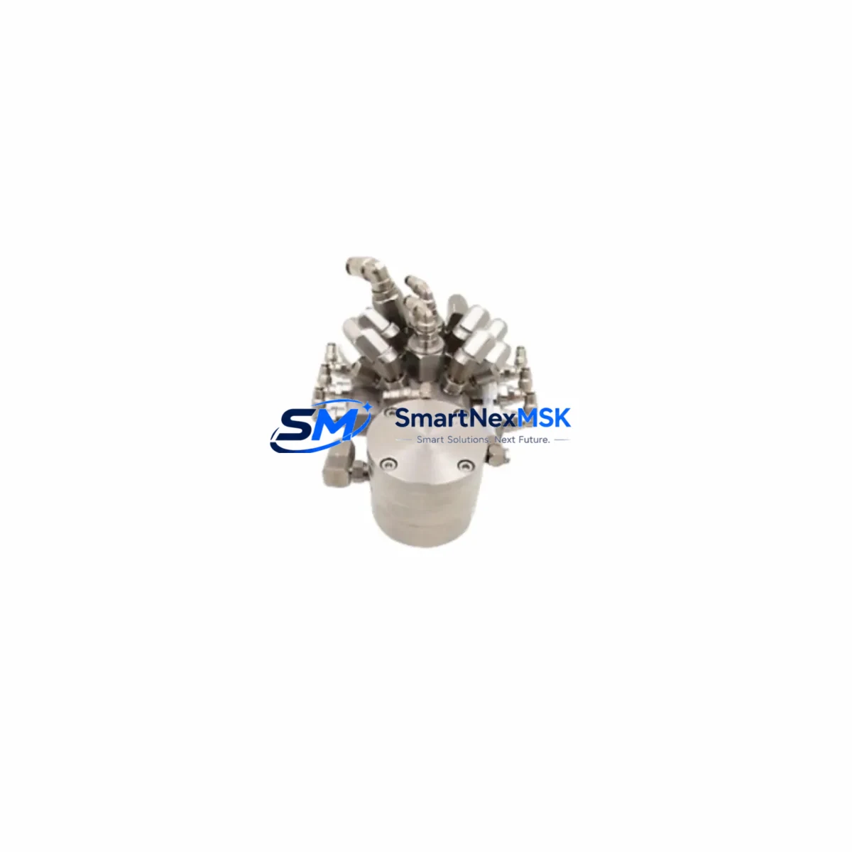
ABB PRDR0046100Z-03 Maintenance-Ready Spare PCB-R0461000: Spare Replacement & Industrial Downtime Risk Control
The ABB PRDR0046100Z-03 is an original-specification pressure control valve PCB designed for the PCB-R0461000 series in ABB industrial automation systems. For maintenance engineers and procurement teams managing continuous production environments, sourcing a verified spare for this board is a critical step in minimizing unplanned downtime. Whether you are executing a scheduled overhaul, responding to a fault alarm, or building a strategic spare parts buffer, the PRDR0046100Z-03 delivers the electrical and mechanical compatibility required for a direct, drop-in replacement without system reconfiguration.
This PCB serves as the core control interface for pressure regulation within ABB valve actuator assemblies. Its failure — whether due to voltage transients, moisture ingress, or component aging — typically manifests as erratic valve positioning, loss of feedback signal, or complete actuator lockout. Rapid identification and replacement of this board is essential to restoring loop integrity and resuming automated process control.
All units supplied by SMARTNEXMSK are sourced from verified industrial channels, individually inspected prior to dispatch, and covered by a 12-month warranty. Long-term supply continuity is supported for legacy system operators and OEM maintenance programs.
Spare Maintenance Table
| Part Number | PRDR0046100Z-03 |
| Brand | ABB |
| Compatible Series | PCB-R0461000 / PCB-R0461000-31 |
| Product Type | Pressure Control Valve PCB |
| Origin | Sweden (ABB) |
| Weight | Approx. 600 g |
| Application | Industrial valve actuator pressure control, process automation loops |
| Installation | Direct board replacement; observe ESD precautions and de-energize circuit before installation |
| Operating Environment | Industrial control cabinet; standard IEC 61010 installation conditions |
| Compatibility Verification | Match full part number including revision suffix (-03) before installation |
| Maintenance Recommendation | Inspect for corrosion, burnt traces, and capacitor bulge during scheduled cabinet inspection |
| Warranty | 12 Months — covers manufacturing defects and functional failure under normal operating conditions |
| Pre-Shipment Testing | Functional verification performed before dispatch |
Maintenance Planning for Continuous Operation
When replacing the PRDR0046100Z-03 PCB in a live production environment, a thorough inspection of the surrounding electrical circuit is strongly recommended. Valve PCB failures are rarely isolated events — they are often preceded or accompanied by stress on adjacent components. Maintenance engineers should treat this replacement as an opportunity to audit the full actuator control loop.
Begin by verifying the 24 VDC or 110/220 VAC power supply module feeding the actuator cabinet. A degraded power supply with excessive ripple is a common root cause of PCB damage. Check the input fuse and circuit breaker for signs of thermal stress or intermittent tripping. Inspect the terminal blocks and field wiring connected to the valve positioner — loose or corroded terminals introduce resistance that can cause erratic feedback signals and accelerate board wear.
Review the analog I/O channel on the associated PLC or DCS controller that handles the valve position setpoint and feedback (typically a 4–20 mA loop). A faulty I/O card can send out-of-range signals that stress the PCB. If the system uses an ABB AC500 PLC or ABB Symphony Plus DCS, verify that the relevant analog output module is within calibration tolerance. For systems using HART-enabled positioners, confirm that the HART communication module or multiplexer is functioning correctly, as communication errors can mask underlying PCB faults.
Inspect any signal isolators or signal conditioners in the 4–20 mA loop — these components protect the PCB from ground loops and voltage spikes, and a failed isolator can expose the replacement board to the same fault conditions that damaged the original. Check the relay output module used for valve open/close commands, and verify that the solenoid valve or pilot valve in the actuator assembly is not drawing excessive current that could back-feed into the PCB circuit.
For systems with an HMI panel (such as an ABB CP600 or equivalent) displaying valve status, confirm that the position feedback signal is correctly received after board replacement before returning the loop to automatic mode. If the control cabinet includes a surge protection device (SPD) on the signal or power rail, inspect it for end-of-life indicators. Maintaining a small buffer stock of the PRDR0046100Z-03 alongside compatible power supply boards, fuse sets, and signal isolators is a proven strategy for reducing mean time to repair (MTTR) in high-availability process plants.
Site Replacement Workflow
Step 1 — Isolation: De-energize the actuator cabinet and lock out / tag out (LOTO) the power source. Confirm zero voltage at the PCB terminals using a calibrated multimeter.
Step 2 — Documentation: Photograph the existing wiring and connector positions before removal. Record the full part number including the revision suffix (PRDR0046100Z-03) to confirm the replacement board matches exactly.
Step 3 — ESD Precautions: Use an anti-static wrist strap and ESD-safe mat. The PRDR0046100Z-03 contains sensitive analog circuitry susceptible to electrostatic discharge.
Step 4 — Board Removal & Installation: Disconnect all connectors in sequence, remove the board, and install the replacement. Reconnect all terminals per the documented wiring layout. Do not force connectors — verify keying alignment before seating.
Step 5 — Power-Up & Verification: Re-energize the cabinet and observe the system startup sequence. Verify that the valve position feedback signal is within the expected 4–20 mA range. Confirm correct valve travel from 0% to 100% under manual command from the HMI or engineering workstation.
Step 6 — Return to Automatic: Once functional verification is complete, return the control loop to automatic mode and monitor for at least one full process cycle before signing off the maintenance record.
This workflow supports legacy system continuity, reduces technician error during emergency replacements, and ensures the replacement board operates within its rated parameters from first power-up.
Spare Parts Support FAQ
Q1: Is the PRDR0046100Z-03 compatible with all PCB-R0461000 series variants?
The PRDR0046100Z-03 is designed for the PCB-R0461000 and PCB-R0461000-31 series. Always verify the full part number including the revision suffix (-03) against your existing board before ordering. If you are replacing a different revision (e.g., -01 or -02), contact our technical team to confirm cross-compatibility.
Q2: What is included in the 12-month warranty?
The warranty covers manufacturing defects and functional failure under normal operating conditions for 12 months from the date of dispatch. Each unit undergoes pre-shipment functional testing. Warranty claims are supported with replacement or refund, subject to inspection of the returned unit.
Q3: How quickly can this spare be dispatched for emergency maintenance?
In-stock units are dispatched within 1–2 business days. For urgent requirements, contact [email protected] or call +86 18259474341 to confirm real-time stock availability and expedited shipping options.
Q4: Can SMARTNEXMSK support long-term supply for legacy ABB systems?
Yes. We maintain ongoing sourcing relationships for discontinued and hard-to-find ABB spare parts. For planned maintenance programs or annual procurement contracts requiring multiple units of the PRDR0046100Z-03 or related PCB-R0461000 series components, we can provide volume pricing and reserved stock arrangements.
© 2026 SMARTNEXMSK. All rights reserved.
Original Source: https://smartnexmsk.com
Contact: [email protected] | +86 18259474341



