
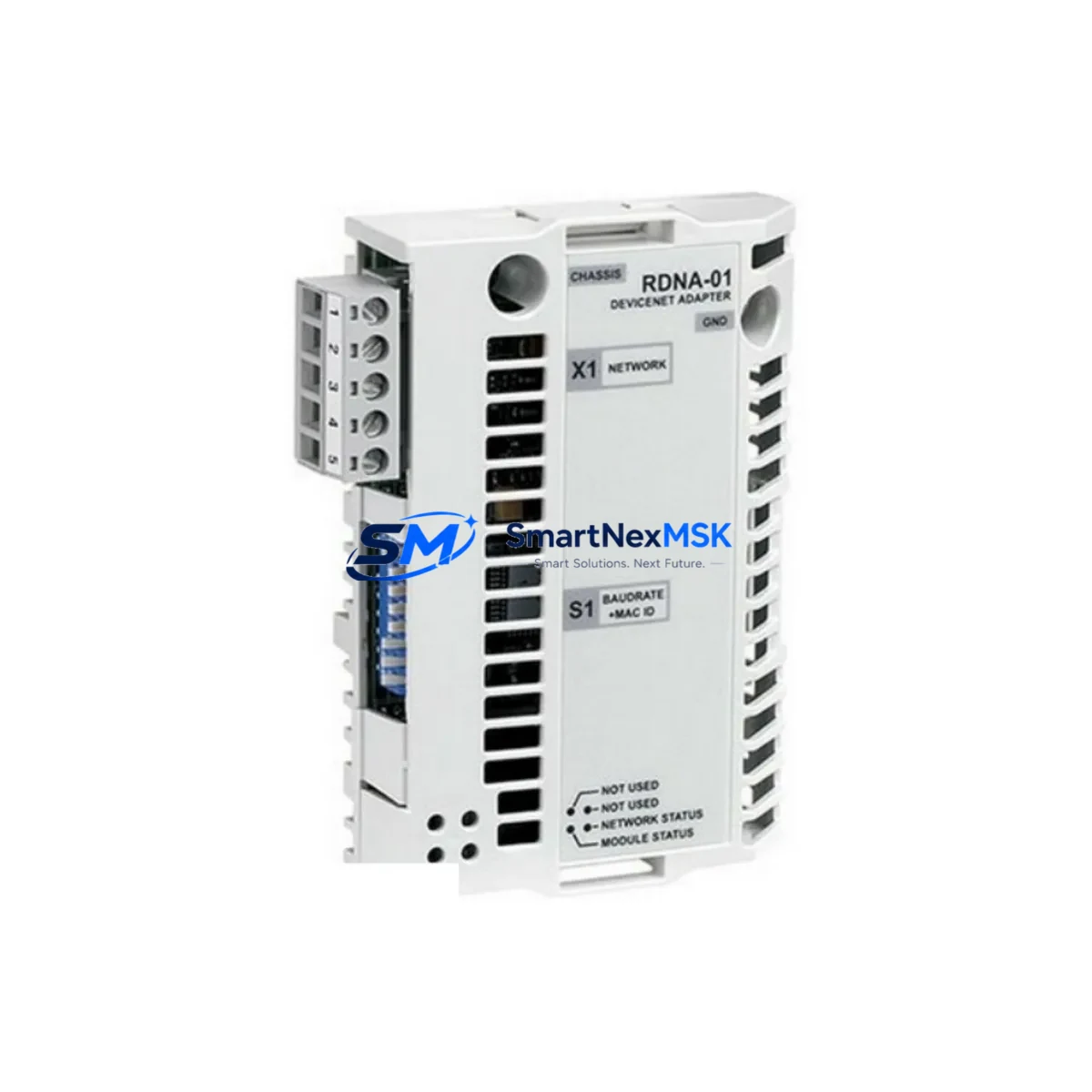
ABB RDNA-01 64606891 Retrofit-Ready DeviceNet Adapter for ACS800 Control Systems
The ABB RDNA-01 (part number 64606891) is a DeviceNet fieldbus adapter module engineered for seamless integration with the ABB ACS800 series variable frequency drives. As legacy ACS800 installations age and original communication modules reach end-of-life, the RDNA-01 has become a critical retrofit component for engineers tasked with modernizing drive communication infrastructure without replacing the entire drive cabinet. Whether you are migrating from an older RDNA-00 variant, recovering from a failed fieldbus node, or upgrading a multi-drive line to a unified DeviceNet topology, the RDNA-01 provides a verified drop-in replacement path with minimal downtime exposure.
This module mounts directly onto the ACS800 drive’s option slot, interfacing with the drive’s internal DDCS (Drive-to-Drive Communication System) backplane. Before installation, engineers should confirm the drive firmware version supports the RDNA-01 parameter set — particularly if the host drive was previously running an RDNA-00 or an RMBA-01 Modbus adapter in the same slot. Parameter group 51 (Fieldbus Adapter) must be reconfigured after module swap, and the DeviceNet node address and baud rate must be set via the drive’s control panel or the DriveWindow Light PC tool before the network master can establish a connection.
Power supply verification is a mandatory pre-installation step. The ACS800 internal 24 VDC auxiliary supply must be confirmed within tolerance before the RDNA-01 is seated. In retrofit scenarios where the control cabinet also houses an ACS800-04 or ACS800-07 regenerative unit, the shared 24 V rail load must be recalculated to account for the additional fieldbus module draw. Terminal wiring on the DeviceNet connector (5-pin open-style) should follow the standard CAN_H / CAN_L / SHIELD / V+ / V− pinout, and network termination resistors (120 Ω) must be confirmed at both ends of the trunk line.
Upgrade Compatibility Table
| Parameter | Detail |
|---|---|
| Compatible Drive Series | ABB ACS800 (all frame sizes, single and multi-drive) |
| Replaces / Supersedes | RDNA-00, RDNA-01 (earlier firmware revisions) |
| Communication Protocol | DeviceNet (CAN-based, IEC 62026-3) |
| Installation Interface | ACS800 option slot (DDCS backplane) |
| Node Address Setting | Via drive panel or DriveWindow Light (Parameter 51.01) |
| Baud Rate Support | 125 kbps / 250 kbps / 500 kbps (auto-detect capable) |
| Power Requirement | 24 VDC from drive internal supply |
| Terminal Connector | 5-pin DeviceNet open-style (CAN_H, CAN_L, SHIELD, V+, V−) |
| Commissioning Tool | DriveWindow Light, ACS800 control panel (CDP312R) |
| Retrofit Complexity | Low — direct slot replacement, parameter reconfiguration required |
| Warranty | 12 Months from date of shipment |
| Condition | New / Surplus New / Tested Refurbished (specify on order) |
Retrofit Planning for Existing Automation Systems
A successful RDNA-01 retrofit begins well before the module arrives on site. In a typical ACS800-based conveyor or pump control system, the drive communicates with a PLC — commonly an ABB AC500 PM573 or PM591 controller — via a DeviceNet scanner card such as the ABB CI504-PNIO or a third-party DeviceNet master. The RDNA-01 appears on the network as a standard DeviceNet slave device, and its EDS (Electronic Data Sheet) file must be imported into the PLC programming environment (Automation Builder or equivalent) to correctly map process data objects (PDOs).
In multi-drive panels where several ACS800 units share a common control cabinet, each drive requires its own RDNA-01 with a unique node address. Engineers should document the existing node map before any swap to avoid address conflicts. If the panel also includes an ACS800 with an RMIO-11 control board running an older firmware, a firmware upgrade may be required before the RDNA-01 can be recognized — this should be validated against ABB firmware compatibility matrices prior to ordering.
For systems that previously used an RDNA-01 alongside an RAIO-01 analog I/O extension module or an RDIO-01 digital I/O extension, these companion modules remain fully compatible and do not require replacement during the fieldbus adapter swap. Similarly, if the drive cabinet includes an ACS800 with an NBRA-6x brake chopper unit or an NINT-41 inverter module, the RDNA-01 retrofit does not affect those power-stage components.
HMI integration is another key consideration. If the existing system uses an ABB CP600 panel or a third-party HMI connected via the drive’s RS-485 port (using the RMBA-01 Modbus adapter in a parallel slot), the HMI communication path is independent of the DeviceNet fieldbus and will not be disrupted by the RDNA-01 installation. However, if the HMI reads drive status via the PLC over DeviceNet, the PLC program’s I/O mapping must be verified after the new module is commissioned to ensure all drive status words and control words are correctly addressed.
Outgoing shipment testing is performed on every RDNA-01 unit before dispatch. Each module is powered up, node address and baud rate are configured, and a live DeviceNet network scan is conducted to confirm the module enumerates correctly as a DeviceNet slave. A test report is available upon request. All units ship with a 12-month warranty covering manufacturing defects and functional failures under normal operating conditions.
Downtime Control During System Migration
Minimizing production downtime during an RDNA-01 swap requires a structured hot-swap protocol. The recommended approach is to pre-configure the replacement module off-line using a bench test setup — a 24 VDC bench supply, a DeviceNet USB adapter (such as the Kvaser Leaf Light or equivalent), and the drive’s parameter backup file exported via DriveWindow Light. Node address and baud rate are set and verified before the module is brought to the machine.
On the day of the swap, the PLC program should be placed in a controlled stop state rather than an emergency stop, allowing the DeviceNet master to gracefully remove the failed node from the network scan list. The ACS800 drive should be powered down via the main isolator, the faulty RDNA-01 removed, and the pre-configured replacement seated in the same option slot. After power restoration, the drive’s parameter group 51 should be verified — particularly parameters 51.01 (node address), 51.02 (baud rate), and 51.03 (communication profile) — before the PLC is returned to run mode.
Original program logic in the PLC does not require modification if the replacement RDNA-01 is configured with identical node address and communication profile settings. The DeviceNet master will re-establish the connection automatically once the node is detected on the network. Field commissioning time for a straightforward like-for-like replacement is typically under 30 minutes, making the RDNA-01 one of the most time-efficient retrofit options in the ACS800 ecosystem.
Retrofit Support FAQ
Q1: Is the RDNA-01 64606891 a direct drop-in replacement for the RDNA-00?
Yes, the RDNA-01 is the successor to the RDNA-00 and installs in the same ACS800 option slot. However, parameter group 51 must be reconfigured after the swap, as the RDNA-01 uses an updated parameter set. Verify drive firmware compatibility before installation — drives running firmware versions below 7.x may require a firmware update.
Q2: What commissioning steps are required after installing the RDNA-01?
After seating the module, power up the drive and navigate to parameter group 51 via the CDP312R control panel or DriveWindow Light. Set parameter 51.01 (node address), 51.02 (baud rate), and confirm 51.03 (communication profile) matches your PLC’s DeviceNet scanner configuration. Perform a network scan from the PLC to verify the drive appears as an active node before returning the system to production.
Q3: Can the RDNA-01 be used in ACS800 multi-drive systems with a shared DC bus?
Yes. In ACS800 multi-drive configurations using a shared DC bus (e.g., ACS800-104 or ACS800-304 cabinet drives), each inverter unit requires its own RDNA-01 with a unique DeviceNet node address. The shared DC bus and common rectifier unit (such as the ISU — Intelligent Supply Unit) are not affected by the fieldbus adapter configuration.
Q4: What does the 12-month warranty cover, and what is the return process?
The 12-month warranty covers all manufacturing defects and functional failures under normal operating conditions from the date of shipment. If a unit fails within the warranty period, contact our sales team with the order reference and a description of the fault. We will arrange a replacement dispatch or repair at no additional cost. Pre-shipment test reports are available for all units upon request.
© 2026 SMARTNEXMSK. All rights reserved.
Original Source: https://smartnexmsk.com
Contact: [email protected] | +86 18259474341



