
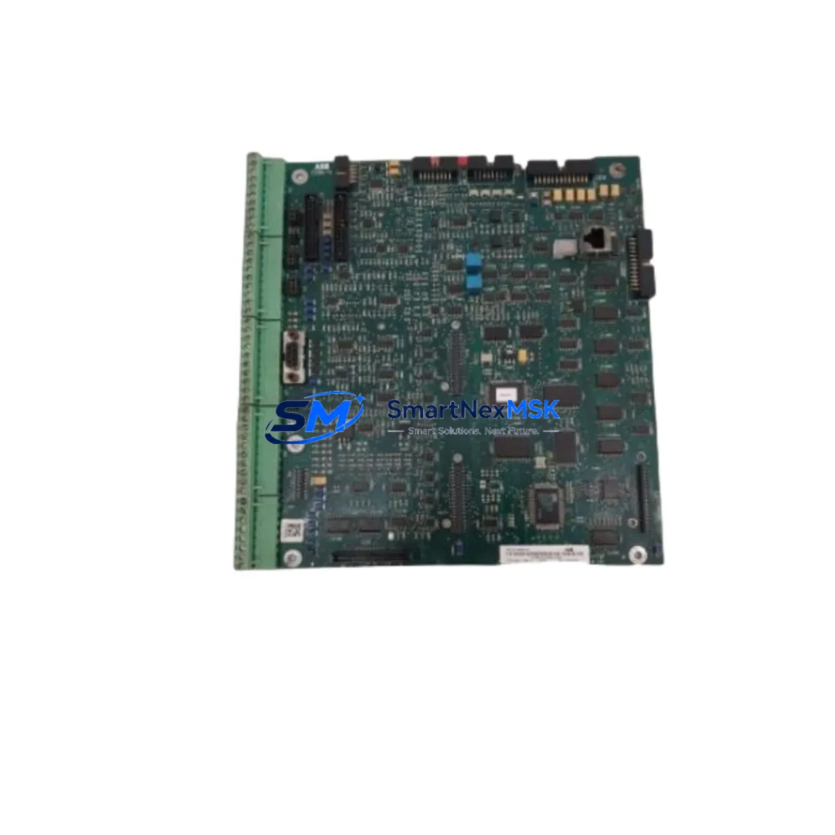
ABB SDCS-CON-4-COAT 3ADT313900R1001 Spare for DCS500 Automation
The ABB SDCS-CON-4-COAT (part number 3ADT313900R1001) is the original control board at the heart of the DCS500 series DC drive platform — one of ABB’s most widely deployed variable-speed drive families in heavy industrial environments. When this board fails, the entire drive goes offline, halting motors, conveyors, winders, extruders, or hoists that depend on it. Sourcing a verified, tested replacement quickly is the single most effective action a maintenance team can take to restore production and minimize unplanned downtime costs.
At SMARTNEXMSK, every SDCS-CON-4-COAT unit is inspected, function-tested, and shipped with a 12-month warranty. We maintain standing stock to support emergency same-day dispatch and long-term planned maintenance programs alike. Whether you are executing a scheduled overhaul, responding to a fault alarm, or building a critical-spares inventory for aging DCS500 drives, this board ships ready to install.
Spare Maintenance Table
| Parameter | Specification |
|---|---|
| Part Number | 3ADT313900R1001 |
| Model | SDCS-CON-4-COAT |
| Brand | ABB |
| Compatible Series | DCS500 DC Drive (DCS501, DCS502) |
| Board Function | Main Control & Regulation Board |
| Supply Voltage | 24 VDC (from SDCS-POW-4 power supply board) |
| Communication Interface | SDCS-COM-8 / SDCS-COM-81 fieldbus adapter slot |
| Conformal Coating | Yes (COAT variant — suitable for humid/dusty environments) |
| Origin | Germany |
| Condition | Original, New or Tested Surplus |
| Application Environment | Industrial — steel, paper, mining, marine, crane, winder |
| Mounting | DCS500 drive chassis, direct board replacement |
| Warranty | 12 Months |
| Shipping | Worldwide — EMS, DHL, FedEx |
| Lead Time | In-stock: 1–3 business days |
Maintenance Planning for Continuous Operation
Replacing the SDCS-CON-4-COAT is rarely an isolated task. Experienced maintenance engineers treat a control board failure as a trigger for a broader inspection of the DCS500 drive cabinet. Before returning the drive to service, the following components should be evaluated in the same maintenance window:
The SDCS-POW-4 power supply board provides the 24 VDC rail that feeds the control board. A degraded SDCS-POW-4 can cause intermittent resets or corrupt parameter memory — replacing the control board without verifying the power supply risks a repeat failure within weeks. Similarly, the SDCS-FEX-2 or SDCS-FEX-2A field excitation board should be checked for output stability, as field current irregularities often accompany armature control faults.
The SDCS-COM-8 or SDCS-COM-81 fieldbus communication module, which plugs into the control board’s adapter slot, should be reseated and tested. Loose or corroded connector contacts between the COM module and the CON-4 board are a common source of intermittent drive trips that are misdiagnosed as control board failures. If the site uses PROFIBUS DP or DeviceNet, verify the network address and baud rate settings after board replacement, as these are stored on the control board itself.
Inspect the SDCS-IOB-3 I/O extension board if the application uses expanded analog or digital I/O. Wiring terminations on the I/O board’s screw terminals should be torqued to specification and checked for oxidation, particularly in humid or coastal environments where the conformal-coated COAT variant is typically specified. Terminal blocks and WAGO or Phoenix Contact rail-mount terminals in the same cabinet should be inspected for loose conductors.
For drives equipped with encoder feedback, verify the SDCS-POS-C or equivalent pulse encoder interface card. Encoder signal integrity is critical for closed-loop speed regulation, and a new control board will not compensate for a degraded encoder cable or failing encoder supply. Check shielding continuity on encoder cables and replace any damaged ferrite cores.
The drive’s thyristor bridge (SCR stack) and associated RC snubber circuits should be tested with a multimeter for forward/reverse conduction symmetry. A shorted or open thyristor will immediately damage a new control board if not identified before power-up. Fuse holders and semiconductor fuses (e.g., ABB OS-series or equivalent) protecting the thyristor bridge must be inspected — replace any fuse that shows signs of heat discoloration even if it has not blown.
Finally, if the site operates an ABB ACS800, ACS600, or other drive types alongside the DCS500, consider aligning the spare-parts strategy across platforms. Stocking a SDCS-CON-4 (non-coated variant) alongside the COAT version ensures coverage for drives installed in standard enclosures, while the COAT variant covers outdoor or wash-down rated cabinets.
Site Replacement Workflow
Step 1 — Pre-replacement verification: Record all drive parameters using the ABB DriveWindow or keypad before powering down. The SDCS-CON-4-COAT stores motor data, PID tuning, ramp settings, and fieldbus configuration. A parameter backup eliminates hours of recommissioning time after board swap.
Step 2 — Safe isolation: Isolate the drive from mains supply and verify zero voltage on the DC bus capacitors using a calibrated meter. The DCS500 DC bus can retain dangerous charge for several minutes after disconnection. Follow site LOTO procedures.
Step 3 — Board removal: Disconnect all ribbon cables and plug-in modules (COM adapter, I/O board) from the existing SDCS-CON-4-COAT. Note cable routing and connector orientation with photographs before removal. Remove the board from the chassis using the appropriate screwdriver.
Step 4 — Inspection and cleaning: Before installing the replacement board, clean the drive chassis interior with dry compressed air. Inspect the backplane connector for bent pins or debris. Check that the chassis earth bonding strap is intact.
Step 5 — Installation and parameter restore: Seat the new SDCS-CON-4-COAT firmly, reconnect all modules and cables, and restore the saved parameter set. Verify motor nameplate data matches the parameter file. Power up in open-loop test mode before reconnecting the load.
Step 6 — Functional test: Run the drive at low speed under no-load conditions and verify speed feedback, current regulation, and fieldbus communication. Confirm fault history is clear before returning the drive to production.
This workflow is compatible with both direct like-for-like replacement of a failed SDCS-CON-4-COAT and planned upgrade from an older SDCS-CON-2 or SDCS-CON-3 board, where the CON-4 variant offers improved diagnostics and expanded I/O capability.
Spare Parts Support FAQ
Q1: Is the SDCS-CON-4-COAT a direct replacement for the SDCS-CON-4 (non-coated)?
Yes. The COAT suffix indicates conformal coating applied to the PCB for enhanced resistance to humidity, condensation, and airborne contaminants. The electrical function, connector layout, and parameter compatibility are identical to the standard SDCS-CON-4. Either variant can be installed in any DCS500 drive chassis without hardware modification.
Q2: How do I verify compatibility with my specific DCS500 drive rating?
The SDCS-CON-4-COAT is compatible across the full DCS500 current range (DCS501 and DCS502 variants, from low-current to high-current frames). Compatibility is determined by the drive’s firmware version rather than its current rating. We recommend confirming the existing firmware revision from the drive’s nameplate or parameter list (parameter 33.01) before ordering, and we can advise on firmware matching if required.
Q3: What testing is performed before shipment?
Each SDCS-CON-4-COAT unit undergoes visual inspection for physical damage, conformal coating integrity check, and functional power-up test on a DCS500 test rig to verify control logic, I/O response, and communication interface operation. A test report is available on request. Units are packed in anti-static ESD bags with foam cushioning for safe international transit.
Q4: What does the 12-month warranty cover, and what is the support process?
The 12-month warranty covers manufacturing defects and functional failure under normal operating conditions from the date of delivery. It does not cover damage caused by incorrect installation, overvoltage events, or physical impact. In the event of a warranty claim, contact [email protected] with the order number and a description of the fault. We will arrange return shipping and provide a replacement or full refund within the agreed lead time.
© 2026 SMARTNEXMSK. All rights reserved.
Original Source: https://smartnexmsk.com
Contact: [email protected] | +86 18259474341



