
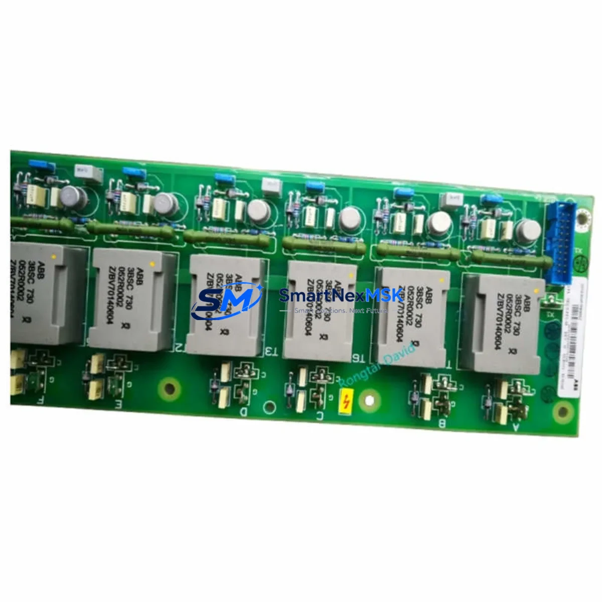
ABB SDCS-PIN-48-SD Retrofit-Ready Interface for DCS500 Control Systems
The ABB SDCS-PIN-48-SD (part number 3BSE004939R1012) is a precision-engineered DC drive interface board designed for seamless integration into ABB DCS500 series DC drive systems. As legacy DCS500 installations age and original components approach end-of-life, the SDCS-PIN-48-SD has become a critical retrofit component for engineers tasked with modernizing existing control architectures without full system replacement. Whether you are managing a planned upgrade or responding to an unplanned drive failure, this board delivers the electrical compatibility, signal integrity, and mechanical fit required for a reliable, low-risk retrofit.
Sourced directly from verified supply channels and subjected to pre-shipment functional testing, each unit is backed by a 12-month warranty covering manufacturing defects and operational failures under normal service conditions. Global logistics support ensures fast dispatch to industrial sites across Asia, Europe, the Middle East, and the Americas.
Upgrade Compatibility Table
| Parameter | Details |
|---|---|
| Compatible Drive Series | ABB DCS500 (DCS501, DCS502, DCS503, DCS504) |
| Part Number | SDCS-PIN-48-SD / 3BSE004939R1012 |
| Interface Type | 48-pin DC drive interface board |
| Mounting / Installation | Direct backplane slot replacement; no mechanical modification required |
| Terminal Wiring | Pin-compatible with original DCS500 wiring harness; verify terminal torque specs before reconnection |
| Communication Compatibility | Compatible with SDCS-COM-1, SDCS-COM-8 fieldbus adapter modules (Profibus, Modbus) |
| Replacement Recommendation | Direct drop-in for failed or end-of-life SDCS-PIN-48-SD boards in DCS500 cabinets |
| Commissioning Notes | Verify drive parameter set (99.01–99.15) after board swap; re-run autotune if motor data is lost |
| Warranty | 12 months from shipment date; covers manufacturing defects under normal operating conditions |
| Pre-Shipment Testing | Functional burn-in test performed on each unit prior to dispatch |
Retrofit Planning for Existing Automation Systems
Replacing the SDCS-PIN-48-SD in an active DCS500 installation requires careful pre-work to avoid extended downtime and protect existing program logic. Before removing the failed board, engineers should document the full drive parameter list using the ABB DriveWindow or DriveWindow Light software connected via the SDCS-COM-8 or a compatible RS-232 programming cable. This ensures that motor nameplate data, speed reference scaling, current limits, and PID tuning values can be restored exactly after the board swap.
On the power side, confirm that the incoming AC supply to the DCS500 cabinet — typically fed through an ABB ACS or external transformer — is isolated and locked out before opening the drive enclosure. The SDCS-PIN-48-SD interfaces directly with the drive’s internal power supply board (commonly the SDCS-POW-1 or SDCS-POW-4), so verifying DC bus discharge is mandatory before handling the interface board. Use a calibrated multimeter to confirm bus voltage has dropped below 50 VDC before proceeding.
Terminal wiring on the SDCS-PIN-48-SD connects to the drive’s analog and digital I/O terminals. Before disconnecting, photograph or map all field wiring — including speed reference inputs (terminals 1–3), digital command inputs (terminals 14–20), and relay output connections. If the existing installation uses an SDCS-IOB-3 or SDCS-IOB-21 I/O extension board, verify that the new interface board’s firmware revision is compatible with the I/O expansion configuration currently in use.
For sites running Profibus DP or Modbus RTU communication, the fieldbus adapter — typically an SDCS-COM-1 for Profibus or SDCS-COM-8 for serial protocols — must remain undisturbed during the board replacement. After reinstalling the SDCS-PIN-48-SD, confirm that the fieldbus node address and baud rate parameters are correctly restored, and verify communication status on the PLC or DCS master side before releasing the drive to automatic control. In Siemens S7 or Allen-Bradley ControlLogix environments, this means checking the GSD file mapping or EDS configuration against the restored drive parameters.
If the DCS500 drive is part of a multi-drive system sharing a common DC bus or coordinated speed reference from an upstream master drive or ABB AC800M controller, ensure that the master-follower communication link is re-established and verified before enabling the drive. Check the SDCS-CON-2 or SDCS-CON-4 control board status LEDs to confirm normal operation after the interface board replacement. For installations with an ABB Panel Bus or APC (Advant Controller) integration, re-validate the drive’s logical address in the control network topology.
Downtime Control During System Migration
Minimizing production downtime during a DCS500 interface board replacement begins with preparation, not execution. The actual board swap typically takes under 30 minutes for an experienced technician; the majority of downtime risk comes from parameter loss, wiring errors, and communication re-commissioning. A structured pre-shutdown checklist — covering parameter backup, wiring documentation, spare parts staging, and coordination with the PLC or DCS operator — can reduce total outage time to under two hours even on complex multi-drive lines.
Where production schedules cannot accommodate a planned outage, consider staging the replacement during a scheduled maintenance window or shift changeover. If the DCS500 drive controls a critical process with no bypass capability, coordinate with the site’s control engineer to implement a temporary manual control mode or hardwired bypass on the downstream motor contactor before initiating the drive shutdown. This preserves process continuity while the interface board is replaced and re-commissioned.
After reinstalling the SDCS-PIN-48-SD and restoring all parameters, perform a no-load test run at reduced speed reference before returning the drive to full automatic control. Verify that speed feedback from the tachometer or encoder — connected through the SDCS-FEX-2 or SDCS-FEX-3 field excitation board — is reading correctly, and confirm that the drive’s current limit and acceleration ramp settings match the pre-failure baseline. Only after a stable no-load run should the motor be reconnected to the mechanical load and the drive released to the control system.
Maintaining a documented retrofit record — including the replaced board’s serial number, the date of replacement, the technician’s name, and the post-commissioning parameter printout — supports future maintenance planning and warranty claim processing. SMARTNEXMSK provides technical support during the commissioning phase for all units supplied under the 12-month warranty program.
Retrofit Support FAQ
Q1: Is the SDCS-PIN-48-SD (3BSE004939R1012) a direct replacement for the original ABB board in DCS500 drives?
Yes. The SDCS-PIN-48-SD supplied by SMARTNEXMSK is a form-fit-function compatible replacement for the original ABB board. It uses the same 48-pin connector layout, the same backplane mounting footprint, and is electrically compatible with all DCS500 series variants (DCS501, DCS502, DCS503, DCS504). No mechanical modification or wiring adaptation is required for a standard replacement.
Q2: What commissioning steps are required after installing the replacement board?
After physical installation, restore the full drive parameter set from your pre-shutdown backup using DriveWindow or DriveWindow Light. Re-enter motor nameplate data (parameters 99.01–99.06) if the parameter memory was lost. Run the drive’s autotune function to re-calibrate current control. Verify fieldbus communication status if the drive uses SDCS-COM-1 or SDCS-COM-8 adapters. Perform a no-load test run before reconnecting the mechanical load.
Q3: How do I verify wiring compatibility before powering up the drive after the board swap?
Before energizing, use a continuity tester to verify that all field wiring connections match the original terminal documentation. Pay particular attention to the analog speed reference input (terminals 1–3), the enable and run command inputs (terminals 14–20), and the relay output wiring. Confirm that the DC bus has fully discharged (below 50 VDC) before handling any internal connections, and verify that the SDCS-POW-1 or SDCS-POW-4 power supply board connections are secure before applying power.
Q4: What does the 12-month warranty cover, and how is a warranty claim processed?
The 12-month warranty covers manufacturing defects and component failures under normal operating conditions from the date of shipment. It does not cover damage caused by incorrect installation, overvoltage events, environmental contamination, or unauthorized modification. To initiate a warranty claim, contact SMARTNEXMSK with the unit’s serial number, purchase order reference, and a description of the failure symptom. Replacement or repair will be arranged within the warranty period at no additional cost for qualifying claims.
© 2026 SMARTNEXMSK. All rights reserved.
Original Source: https://smartnexmsk.com
Contact: [email protected] | +86 18259474341



