
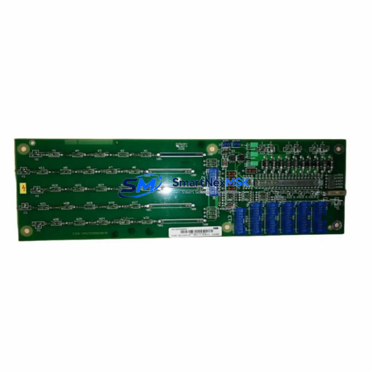
ABB SDCS-PIN-51 Retrofit-Ready Pulse Interface for DCS800 Control Systems
The ABB SDCS-PIN-51 is a pulse encoder interface card engineered for the DCS800 series DC drive platform, purpose-built to support legacy system modernization, discontinued spare part replacement, and control cabinet upgrades across industrial automation environments. Whether you are migrating from an aging DCS500 or DCS400 drive system, replacing a failed encoder feedback board, or expanding an existing DCS800 installation, the SDCS-PIN-51 delivers the signal conditioning, encoder compatibility, and backplane integration required for a smooth, low-risk retrofit.
For engineers and procurement teams managing aging DC drive infrastructure, the SDCS-PIN-51 addresses one of the most common pain points in legacy system maintenance: sourcing a verified, tested replacement for a discontinued pulse interface module without compromising drive performance or encoder signal integrity. This card supports incremental encoder inputs and provides the speed feedback loop essential for closed-loop DC motor control in demanding industrial applications including paper mills, steel rolling lines, crane drives, and extruder systems.
Upgrade Compatibility Table
| Parameter | Details |
|---|---|
| Compatible Platform | ABB DCS800 Series DC Drives |
| Replaces / Upgrades From | DCS500 pulse interface boards, DCS400 encoder cards, legacy SDCS-PIN-4x variants |
| Encoder Input Type | Incremental TTL/HTL encoder, A/B/Z channels |
| Backplane Interface | DCS800 option slot (SDCS-CON-4 control board compatible) |
| Supply Voltage | +24 VDC from drive internal bus |
| Communication Compatibility | Compatible with DDCS fiber optic link, PROFIBUS-DP via RDCO-0x adapter |
| Installation Requirement | Slot into DCS800 option slot; no external wiring harness required for standard encoder input |
| Retrofit Recommendation | Verify encoder PPR setting in drive parameter group 50 after installation |
| Commissioning Focus | Encoder direction, speed scaling, zero-speed detection threshold |
| Warranty | 12 Months — covers manufacturing defects and functional failure under normal operating conditions |
Retrofit Planning for Existing Automation Systems
A successful SDCS-PIN-51 retrofit begins well before the card arrives on site. The first step is a thorough audit of the existing control cabinet, including the DCS800 drive firmware version, the SDCS-CON-4 control board revision, and the current encoder wiring topology. In many legacy installations, the encoder cable runs from the motor terminal box through cable trays shared with power conductors — shielding integrity and grounding continuity must be verified before the new pulse interface card is seated.
When replacing a failed or end-of-life pulse interface board from an older DCS500 or DCS400 platform, engineers must account for differences in encoder supply voltage. The SDCS-PIN-51 supports both 5 V and 24 V encoder supply configurations, selectable via onboard jumper settings. Confirm the encoder nameplate voltage before powering the drive to avoid damaging the encoder transducer.
Terminal block wiring on the SDCS-PIN-51 follows the standard DCS800 option card pinout. If the existing installation used a custom wiring harness for the legacy encoder card, a new harness should be fabricated to match the SDCS-PIN-51 terminal layout. Reference the DCS800 Hardware Manual (3ADW000379) for the exact pin assignments for channels A, /A, B, /B, Z, and /Z, as well as the encoder supply and common terminals.
For sites running PROFIBUS-DP communication between the DCS800 and a Siemens S7-300 or S7-400 PLC, the RDCO-02 or RDCO-04 DDCS-to-PROFIBUS adapter must remain in its designated option slot. The SDCS-PIN-51 occupies a separate option slot and does not conflict with the communication adapter. However, after installation, verify that the drive’s parameter 98.02 (Encoder Module Type) is correctly set to recognize the SDCS-PIN-51 and that the encoder pulse count (parameter 50.01) matches the installed encoder’s PPR specification.
Sites using ABB Panel Builder or AC500 PLCs for supervisory control should also verify that the speed reference scaling in the HMI project matches the updated encoder feedback resolution. If the legacy system used a lower-resolution encoder with the old pulse interface card, upgrading to a higher-PPR encoder in conjunction with the SDCS-PIN-51 may require HMI tag rescaling and drive parameter adjustments to maintain accurate speed display and setpoint tracking.
For I/O expansion during the retrofit, the SDCS-IOE-1 I/O extension module and SDCS-DSL-4 digital speed limit board are commonly installed alongside the SDCS-PIN-51 in multi-drive cabinet upgrades. The NTAC-02 pulse encoder interface module is another frequently referenced component in DCS800 retrofit bills of materials, particularly for high-speed encoder applications. When the retrofit scope includes a full control board replacement, the SDCS-CON-4 is the standard control board for DCS800 drives and must be confirmed as present and compatible before the SDCS-PIN-51 is installed. In cabinet configurations where the DCS800 is paired with an ACS800 inverter for regenerative braking, the RINT-5611C rectifier interface board may also require inspection to ensure the DC bus voltage feedback remains within calibrated limits after the encoder retrofit.
Downtime Control During System Migration
Minimizing production downtime during a pulse interface card replacement requires a structured pre-outage preparation protocol. Before the scheduled maintenance window, download and archive the complete drive parameter set using DriveWindow Light or Drive Composer Pro. This backup preserves all tuning values, speed reference ramps, current limits, and encoder configuration parameters, ensuring that if the commissioning process encounters an unexpected issue, the drive can be restored to its previous state within minutes.
During the physical swap, the DCS800 main contactor should be opened and the DC bus fully discharged before the option card slot cover is removed. Capacitor discharge time for DCS800 drives varies by frame size — consult the drive’s safety instructions for the minimum wait time before touching internal components. The SDCS-PIN-51 is a hot-swap-capable option card in some firmware revisions, but field practice recommends a full power-down cycle to avoid transient encoder signal errors during initialization.
After the card is seated and the encoder cable is reconnected, perform a controlled no-load test run at reduced speed reference (typically 10–15% of rated speed) to verify encoder direction and signal quality before restoring full production speed. Use the drive’s diagnostic parameter group (group 01) to monitor actual speed feedback in real time. If the speed feedback sign is inverted, correct it via parameter 50.02 (Encoder Direction) rather than physically swapping encoder cable pairs, which preserves the original wiring documentation.
For multi-drive systems where the DCS800 is part of a coordinated line drive configuration — such as a paper machine with multiple section drives synchronized via DDCS fiber optic master-follower links — the master drive’s speed reference must be held constant during the follower drive’s retrofit window. Coordinate with the process control team to confirm that the line speed reference from the AC500 or S7 PLC is locked before the follower drive is taken offline. This approach maintains web tension and prevents material breaks during the transition.
Retrofit Support FAQ
Q1: Is the SDCS-PIN-51 a direct drop-in replacement for older ABB pulse interface cards used in DCS500 systems?
The SDCS-PIN-51 is designed for the DCS800 platform and is not mechanically or electrically interchangeable with DCS500 option cards. However, it is the correct replacement when upgrading a DCS500-based system to a DCS800 drive, which is the recommended migration path for DCS500 end-of-life installations. The encoder wiring and PPR settings must be reconfigured during commissioning to match the DCS800 parameter structure.
Q2: What encoder types are compatible with the SDCS-PIN-51, and how do I verify compatibility before ordering?
The SDCS-PIN-51 supports incremental encoders with TTL (5 V) or HTL (24 V) output signals, A/B/Z channel configuration, and pulse counts from 256 to 4096 PPR (configurable via drive parameters). Confirm the encoder’s output voltage level, channel configuration, and PPR from the encoder nameplate or datasheet before ordering. If the existing encoder is a resolver or absolute encoder, additional interface modules are required.
Q3: How is the SDCS-PIN-51 tested before shipment, and what does the 12-month warranty cover?
Each SDCS-PIN-51 unit supplied by SMARTNEXMSK undergoes functional verification testing prior to shipment, including encoder signal simulation, supply voltage check, and backplane connector integrity inspection. The 12-month warranty covers manufacturing defects and functional failure under normal operating conditions. It does not cover damage resulting from incorrect installation, overvoltage, or physical impact. Warranty claims are processed with return shipment support and replacement dispatch within 5 business days.
Q4: Can the SDCS-PIN-51 be used in a DCS800 drive that is also running a PROFIBUS-DP communication adapter?
Yes. The SDCS-PIN-51 occupies a dedicated encoder option slot on the DCS800 and does not conflict with the RDCO-02 or RDCO-04 PROFIBUS-DP adapter installed in the communication option slot. Both cards can operate simultaneously. After installation, verify drive parameters 98.02 and 50.01 to ensure the encoder module is recognized and the pulse count is correctly configured for your application.
© 2026 SMARTNEXMSK. All rights reserved.
Original Source: https://smartnexmsk.com
Contact: [email protected] | +86 18259474341



