
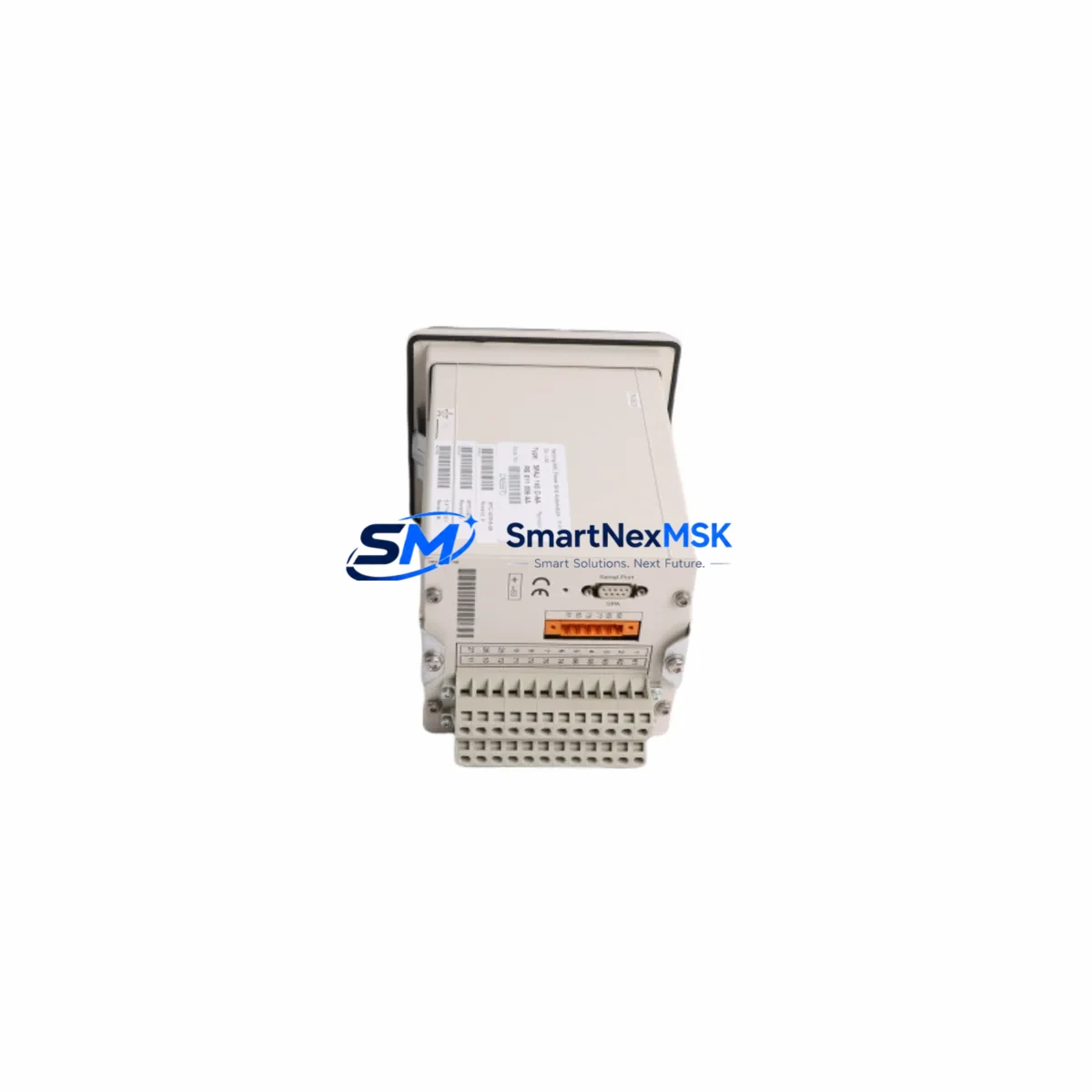
ABB SPAJ140C-AA Maintenance-Ready Spare SPAJ 140C Automation
The ABB SPAJ140C-AA is a combined overcurrent and earth-fault protection relay belonging to ABB’s proven SPAJ 140C series — a cornerstone component in medium-voltage switchgear panels, motor control centers, and feeder protection circuits across power generation, petrochemical, water treatment, and heavy manufacturing facilities. When this relay reaches end-of-life or exhibits trip anomalies, every minute of unplanned downtime translates directly into production loss and safety risk. Sourcing a verified, original-specification replacement is the fastest path to restoring system integrity and resuming normal operations.
This listing provides a maintenance-ready, original-specification SPAJ140C-AA unit, pre-tested before dispatch, backed by a 12-month warranty, and available for rapid worldwide shipment. Whether you are executing a planned annual overhaul, responding to a nuisance trip event, or building a strategic spare-parts buffer for aging SPAJ 140C-equipped switchgear, this unit is ready to deploy.
Spare Maintenance Table
| Parameter | Specification / Detail |
|---|---|
| Part Number / SKU | SPAJ140C-AA |
| Brand | ABB |
| Series | SPAJ 140C |
| Product Type | Combined Overcurrent & Earth-Fault Protection Relay |
| Protection Functions | Phase overcurrent (3×), Earth-fault overcurrent, Definite-time & IDMT characteristics |
| Rated Auxiliary Voltage | 24–240 V AC/DC (wide-range input) |
| Current Input | 1 A / 5 A selectable (CT secondary) |
| Output Contacts | Trip relay + signal relay (potential-free) |
| Communication | SPA-bus (optional LON/Modbus via add-on module) |
| Mounting | Flush panel / rack mount, 4U form factor |
| Operating Temperature | −10 °C to +55 °C |
| Ingress Protection | IP 54 (front panel) |
| Country of Origin | Germany |
| Compatibility | Direct replacement for SPAJ 140C series; compatible with ABB MicroSCADA, SPA-bus RTU, and third-party SCADA via serial gateway |
| Condition | Original, new or refurbished-to-spec; pre-tested before shipment |
| Warranty | 12 Months — covers manufacturing defects and functional failure under normal operating conditions |
| Lead Time | In-stock units ship within 1–3 business days; ex-stock worldwide |
| Maintenance Recommendation | Inspect auxiliary voltage supply, CT wiring, and trip circuit continuity at every scheduled outage; replace relay if self-diagnostic LED indicates persistent fault |
Maintenance Planning for Continuous Operation
A protection relay replacement is rarely an isolated task. When a SPAJ140C-AA is removed from service — whether due to a confirmed internal fault, a failed self-test, or a scheduled lifecycle replacement — the surrounding electrical circuit deserves equal scrutiny. Maintenance engineers and procurement teams should treat this event as an opportunity to audit the entire protection loop and pre-empt secondary failures.
Begin with the auxiliary power supply: the SPAJ140C-AA draws its operating voltage from the panel’s DC bus or UPS-backed AC rail. Verify that the associated 24 VDC or 110 VDC panel power supply module is within voltage tolerance and that its output capacitors show no signs of aging. A marginal power supply is a common root cause of relay self-test failures that are incorrectly attributed to the relay itself.
Next, inspect the current transformer (CT) secondary wiring and terminal blocks. Loose or corroded connections on the CT circuit can introduce measurement errors that cause nuisance trips or, worse, blind the relay to genuine fault conditions. While the panel is de-energized, check the SACO 16D2 or equivalent ABB auxiliary relay used in the trip circuit — these interposing relays age in parallel with the protection relay and should be replaced on the same maintenance cycle.
For panels integrated into an ABB MicroSCADA or SPA-bus network, confirm that the SPA-bus communication cable and the associated SPTE 4E10 or IOPOS optical converter module are functioning correctly. A relay swap that is not followed by a communication re-commissioning step will leave the SCADA system with a stale device address and may suppress alarm annunciation.
If the SPAJ140C-AA is installed in a motor feeder panel, also inspect the SPAM 150C motor protection relay or SPAM 100C units in adjacent feeders — these share the same SPA-bus segment and the same auxiliary supply rail, making them susceptible to the same aging mechanisms. Similarly, check the SPCD 3D53 or SPCD 3D54 signal conditioning modules if analog measurement outputs are used for process monitoring.
For earth-fault protection circuits, verify the integrity of the core-balance CT (Holmgreen connection) and any associated signal isolator or galvanic separator in the measurement loop. Degraded insulation on the CT cable can introduce leakage currents that desensitize the earth-fault element. Finally, review the SPBU 240 or SPBU 340 bus adapter if the relay communicates via a substation automation gateway — firmware compatibility must be confirmed after any relay replacement.
Stocking one or two SPAJ140C-AA units alongside a matched set of auxiliary relays, fuses, and communication adapters is the most cost-effective strategy for facilities that cannot tolerate extended outages. A pre-configured spare, stored in a climate-controlled cabinet with its settings sheet attached, can reduce mean time to repair (MTTR) from hours to under thirty minutes.
Site Replacement Workflow
Step 1 — Isolation & Permit: Obtain a signed permit-to-work. Isolate the feeder circuit breaker and lock out the auxiliary supply to the relay panel. Verify dead using an approved voltage indicator on all terminals.
Step 2 — Settings Documentation: Before removing the old SPAJ140C-AA, photograph or transcribe all protection settings (overcurrent pickup, time multiplier, earth-fault threshold, and communication address) from the relay’s front-panel display or from the SPACOM / PCM600 settings file. This data is essential for commissioning the replacement unit to identical parameters.
Step 3 — Physical Removal: Disconnect the CT secondary leads (short-circuit the CT before opening the secondary circuit), auxiliary supply terminals, trip output wiring, and SPA-bus cable. Remove the relay from its case or rack slot. Retain the old unit for post-mortem analysis if a fault condition triggered the replacement.
Step 4 — Installation of SPAJ140C-AA Replacement: Insert the new unit. Reconnect all wiring in reverse order — SPA-bus first, then auxiliary supply, then CT secondaries (remove short-circuit link last), then trip outputs. Torque all terminal screws to the manufacturer’s specification.
Step 5 — Settings Upload & Verification: Enter all protection settings via the front panel or upload the saved PCM600 / SPACOM configuration file. Verify each setting against the protection coordination study. Confirm the communication address matches the SCADA database entry.
Step 6 — Functional Test: Perform a secondary injection test using a relay test set to verify pickup values, operating times, and trip output continuity. Confirm SCADA alarm and event logging is restored. Re-energize the feeder under supervision and monitor for the first 15 minutes of operation.
Step 7 — Documentation: Update the maintenance log, asset register, and spare-parts inventory. Record the replacement date, new unit serial number, and test results. Schedule the next inspection interval per the facility’s preventive maintenance program.
Spare Parts Support FAQ
Q1: Is this SPAJ140C-AA a direct drop-in replacement for my existing SPAJ 140C relay without any wiring changes?
Yes. The SPAJ140C-AA is a form-fit-function replacement within the SPAJ 140C product family. Terminal assignments, case dimensions, and auxiliary voltage input range are identical to earlier production batches. The only action required after physical installation is re-entering or uploading the protection settings — no wiring modifications are needed.
Q2: How do you verify the unit before shipment, and what does the 12-month warranty cover?
Every unit undergoes a functional pre-shipment test covering auxiliary power-up, self-diagnostic pass, output relay continuity, and (where applicable) communication port response. The 12-month warranty covers manufacturing defects and functional failures under normal operating conditions. It does not cover damage resulting from incorrect installation, overvoltage events, or physical impact. Warranty claims are processed with a return-merchandise authorization (RMA) and typically resolved within 10 business days.
Q3: What is your recommended spare-parts stocking strategy for facilities with multiple SPAJ 140C relays installed?
For facilities with 5 or fewer SPAJ140C-AA units in service, we recommend holding one cold spare. For installations of 6–20 units, hold two spares. For larger fleets or critical infrastructure where any outage carries significant financial or safety consequences, a ratio of one spare per ten installed units is a practical benchmark. Spares should be stored in original packaging, in a dry environment below 40 °C, and inspected annually for any signs of storage degradation.
Q4: Can you supply SPAJ140C-AA units with long-term availability, and do you support obsolescence management?
Yes. We maintain a dedicated inventory of SPAJ 140C series components to support facilities running legacy ABB protection systems beyond the original product’s active manufacturing period. We can provide multi-unit blanket orders, scheduled release shipments, and obsolescence alerts. Contact our team to discuss a long-term supply agreement tailored to your maintenance cycle and budget.
© 2026 SMARTNEXMSK. All rights reserved.
Original Source: https://smartnexmsk.com
Contact: [email protected] | +86 18259474341



