
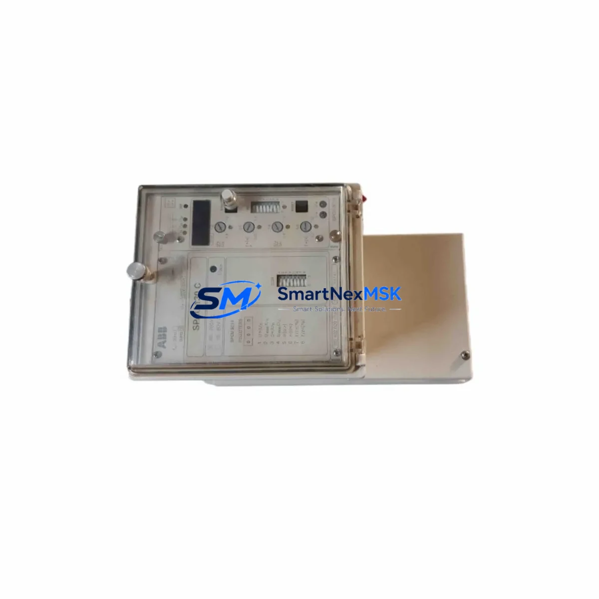
ABB SPAU130 C-AA Retrofit-Ready Voltage Protection Relay: Compatible Upgrade for Legacy SPAU Series Control Systems
The ABB SPAU130 C-AA is a microprocessor-based voltage protection relay engineered for seamless integration into existing ABB SPAU Series protection and control systems. Designed to address the growing demand for discontinued spare parts and legacy system modernization, this relay provides a verified drop-in replacement path for aging protection infrastructure in substations, motor control centers, and industrial switchgear panels. Whether you are managing a planned retrofit or responding to an unplanned failure, the SPAU130 C-AA delivers the compatibility, reliability, and technical precision that industrial automation engineers require.
The SPAU130 C-AA operates as an overvoltage and undervoltage protection relay, monitoring three-phase voltage levels and triggering configurable trip outputs when thresholds are exceeded. Its relay outputs, measurement inputs, and communication interface are fully compatible with the ABB SPAU Series relay platform, making it a direct functional replacement for earlier SPAU130 variants and adjacent models within the same protection family. Engineers migrating from older electromechanical relays or first-generation numerical relays will find the SPAU130 C-AA’s parameterization structure familiar, reducing commissioning time and minimizing the risk of configuration errors during cutover.
Upgrade Compatibility Table
| Parameter | Details |
|---|---|
| Model | ABB SPAU130 C-AA |
| Series Compatibility | ABB SPAU Series (SPAU130, SPAU140, SPAU341 platform) |
| Function | Overvoltage / Undervoltage Protection Relay |
| Auxiliary Supply Voltage | 80–265 V AC/DC (universal input, verify against existing panel supply) |
| Measurement Input | Three-phase voltage via VT secondary (100/110 V nominal) |
| Communication Interface | SPA-bus (ABB proprietary serial protocol); compatible with SPACOM and LON-based SCADA systems |
| Mounting / Form Factor | Flush panel mount, 4U rack compatible; same footprint as SPAU Series predecessors |
| Terminal Wiring | Rear screw terminals; verify terminal block layout against existing wiring diagram before installation |
| Replacement Recommendation | Direct replacement for SPAU130 C variants; functional replacement for SPAU130 A/B with parameter re-entry |
| Commissioning Focus | Voltage threshold settings, trip delay timers, output relay assignment, SPA-bus node address |
| Warranty | 12 Months from date of shipment |
Retrofit Planning for Existing Automation Systems
A successful retrofit of the SPAU130 C-AA into an existing protection panel requires systematic pre-installation verification across several engineering disciplines. Before removing the failed or obsolete relay, engineers should document the existing SPA-bus node address assigned to the unit, as this address must be replicated on the replacement module to maintain communication continuity with the upstream SPACOM communication module or equivalent SPA-bus master. Loss of the node address mapping will cause the SCADA system or DCS to lose visibility of the protection relay, requiring re-configuration of the communication database.
Terminal wiring is a critical checkpoint. The SPAU130 C-AA uses a rear-mounted screw terminal block. Before disconnection, photograph or transcribe the existing wiring layout, paying particular attention to the voltage transformer secondary connections, trip output relay wiring to the circuit breaker shunt trip coil, and the auxiliary supply input terminals. In panels where the auxiliary supply is derived from a shared DC bus — often fed by an ABB SACO or equivalent battery-backed DC power supply module — confirm that the supply voltage and polarity are within the relay’s specified input range.
For systems where the SPAU130 C-AA is installed alongside other SPAU Series relays — such as the SPAU341 overcurrent and earth fault relay or the SPAJ140 combined overcurrent and earth fault relay — verify that the SPA-bus segment addressing does not conflict after replacement. In multi-relay panels, the SPA-bus daisy chain topology means that a misconfigured node address on the SPAU130 C-AA can disrupt communication to all downstream relays on the same segment.
Where the existing protection scheme includes an ABB REF615 or REM615 feeder protection relay operating in parallel with the SPAU Series relays, confirm that the voltage protection functions are not duplicated across both platforms after the retrofit. Overlapping protection zones with mismatched trip delay settings can cause nuisance tripping or, conversely, protection gaps during fault conditions.
For panels that include an ABB SPAD346 or SPAM150C motor protection relay in the same control cabinet, the retrofit of the SPAU130 C-AA should be coordinated with a review of the overall protection coordination study to ensure that voltage-related trip signals are correctly routed and that interlocking logic between the voltage relay and the motor protection relay remains intact after the hardware change.
If the existing panel uses an ABB Panel Builder or a third-party HMI for local operator interface, verify that the HMI display pages referencing the SPAU130 C-AA’s measured values and alarm status are still correctly mapped after the relay replacement. In some legacy installations, HMI pages are hard-coded to specific SPA-bus node addresses or relay register maps; a firmware version difference between the old and new relay may require HMI page updates to correctly display voltage measurements and relay status flags.
Programming cable access is also a consideration. The SPAU130 C-AA is parameterized using the front panel keypad or via the SPA-bus interface using ABB’s VAMPSET or equivalent relay setting tool. Ensure that the commissioning engineer has access to the original relay setting file or protection coordination study before beginning parameter entry on the replacement unit. Where original setting files are unavailable, settings must be reconstructed from the protection coordination study or from the relay test records held by the site’s electrical maintenance team.
Downtime Control During System Migration
Minimizing unplanned downtime during a voltage protection relay replacement requires a structured cutover procedure. The recommended approach is to prepare the SPAU130 C-AA fully before taking the existing relay out of service: pre-enter all protection settings, configure the SPA-bus node address, and bench-test the relay’s trip output function using a secondary injection test set. This pre-commissioning step ensures that the replacement relay is ready for immediate installation and reduces the live outage window to the time required for physical swap and wiring reconnection only.
Where the process cannot tolerate any interruption to voltage monitoring — for example, in critical substation feeders or continuous-process industrial plants — consider implementing a temporary bypass scheme using a portable voltage monitoring relay connected in parallel with the existing installation. This allows the failed relay to be removed and the SPAU130 C-AA to be installed and commissioned without exposing the protected equipment to an unmonitored voltage condition.
After installation, perform a functional verification test by injecting a test voltage above and below the configured trip thresholds and confirming that the relay’s output contacts operate within the specified time delay. Verify that the trip signal is correctly received by the circuit breaker and that the SCADA system registers the relay’s status change. Document the as-left settings and test results in the site’s maintenance management system before returning the protection scheme to service.
Original program logic stored in the upstream PLC or DCS — such as an ABB AC500 or ABB Freelance DCS controller — is not affected by the relay replacement, provided that the SPA-bus communication link is restored with the correct node address. Confirm that the DCS analog input channels receiving voltage measurements from the SPAU130 C-AA are reading correctly after the relay is returned to service, and that all alarm and trip annunciations are functioning as expected.
Retrofit Support FAQ
Q1: Is the ABB SPAU130 C-AA a direct drop-in replacement for earlier SPAU130 variants?
The SPAU130 C-AA is a direct mechanical and electrical replacement for other SPAU130 C-suffix variants. Replacement of SPAU130 A or B suffix units requires re-entry of protection settings, as parameter structures may differ between firmware generations. Always compare the relay’s terminal diagram and setting range documentation before installation.
Q2: What commissioning steps are required after installing the SPAU130 C-AA?
After physical installation and wiring reconnection, the following commissioning steps are required: (1) verify auxiliary supply voltage at the relay terminals; (2) confirm SPA-bus node address matches the original relay; (3) enter all protection settings (overvoltage and undervoltage thresholds, trip delay timers, output relay assignments); (4) perform secondary injection testing to verify trip function; (5) confirm SCADA/DCS communication is restored and relay status is correctly displayed.
Q3: Can the SPAU130 C-AA communicate with non-ABB SCADA systems?
The SPAU130 C-AA uses the ABB SPA-bus serial communication protocol. Integration with non-ABB SCADA systems requires an SPA-bus to Modbus or SPA-bus to IEC 60870-5-101/104 protocol converter. Confirm the communication gateway’s compatibility with the SPAU130 C-AA’s register map before deployment.
Q4: What warranty and testing does the SPAU130 C-AA carry?
All SPAU130 C-AA units supplied by SMARTNEXMSK carry a 12-month warranty from the date of shipment. Each unit undergoes pre-shipment functional testing to verify relay output operation, auxiliary supply acceptance, and communication interface integrity. Test records are available upon request. Units are shipped in anti-static protective packaging with full documentation.
© 2026 SMARTNEXMSK. All rights reserved.
Original Source: https://smartnexmsk.com
Contact: [email protected] | +86 18259474341



