
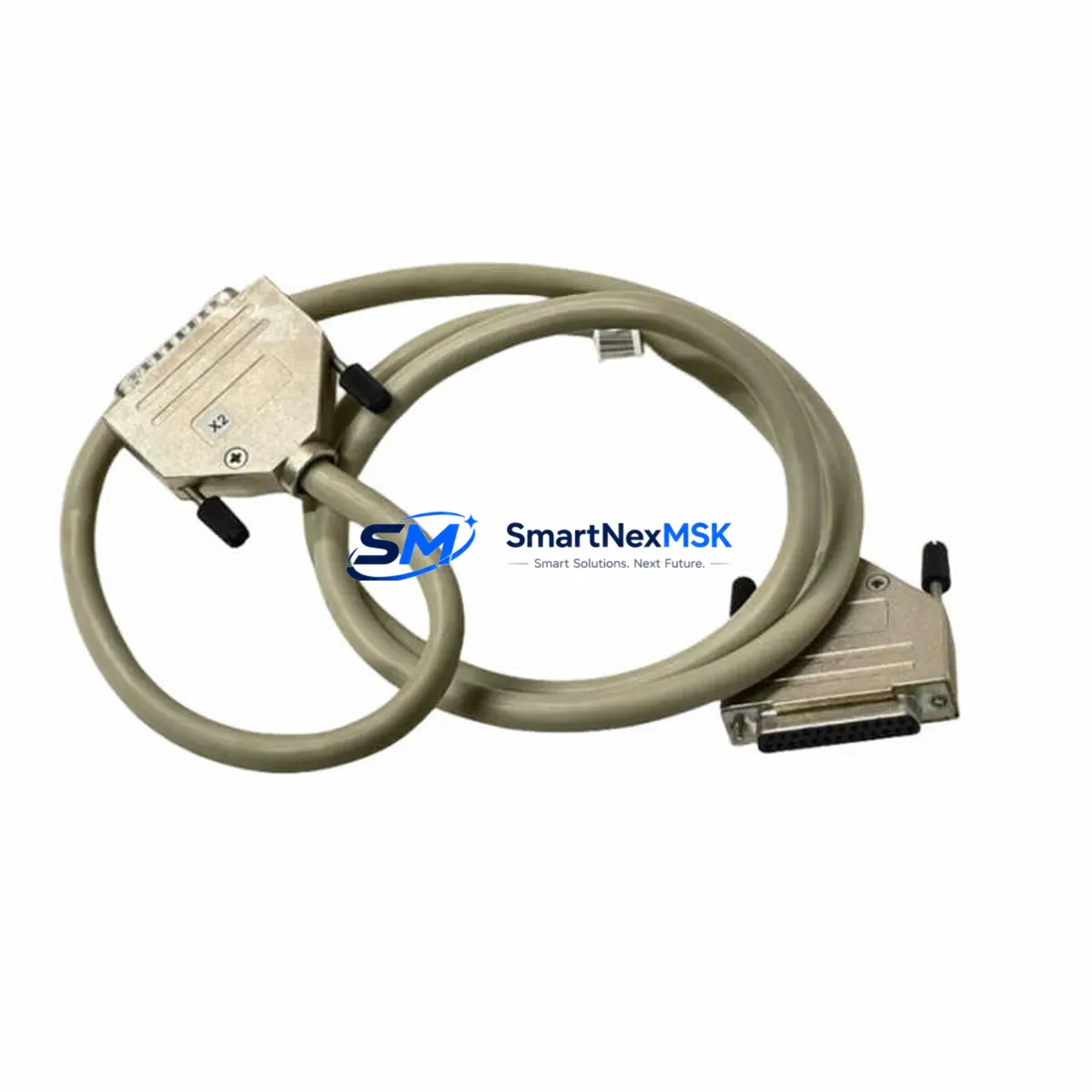
ABB TK801V012 3BSC950089R3 Spare for AC800M Automation: Spare Replacement & Industrial Downtime Risk Control
The ABB TK801V012 (3BSC950089R3) is an original I/O extension cable engineered for the ABB AC800M distributed control system, providing the critical physical link between the AC800M controller and S800 I/O modules mounted on remote or local baseplates. In continuous-process industries — including chemical, oil & gas, power generation, pulp & paper, and water treatment — a degraded or failed extension cable can isolate entire I/O clusters from the controller, triggering unplanned shutdowns and costly production losses. Stocking a verified spare of the TK801V012 is a foundational element of any credible spare-parts strategy for AC800M-based control systems.
This listing supplies the genuine ABB TK801V012 / 3BSC950089R3 — not a generic substitute — sourced through authorized industrial channels, individually tested prior to shipment, and backed by a 12-month warranty. Each unit is inspected for connector integrity, cable shielding continuity, and correct impedance before dispatch, ensuring drop-in replacement without additional commissioning risk.
Spare Maintenance Table
| Parameter | Specification / Detail |
|---|---|
| Part Number | TK801V012 |
| ABB Order Code | 3BSC950089R3 |
| Product Type | I/O Extension Cable |
| Compatible Controller | ABB AC800M (PM851, PM856, PM860, PM861, PM864, PM866) |
| Compatible I/O System | ABB S800 I/O (AI810, AO810, DI810, DO810, DI811, AI820, etc.) |
| Cable Length | 12 m (nominal) |
| Connector Type | Proprietary ABB S800 I/O bus connector, keyed |
| Signal Type | S800 I/O bus (serial, differential) |
| Shielding | Foil + braid, EMI-rated for industrial environments |
| Operating Temperature | 0 °C to +55 °C (storage: −25 °C to +70 °C) |
| Country of Origin | Germany |
| Weight | Approx. 155 g |
| Compatibility Verification | Confirmed for AC800M S800 I/O bus topology |
| Installation | Hot-swap capable with controller in maintenance mode; no tools required |
| Pre-shipment Test | Continuity, shielding, and connector seating verified |
| Warranty | 12 months from date of shipment |
| Lead Time | In-stock units ship within 1–3 business days |
Maintenance Planning for Continuous Operation
When a maintenance or reliability engineer schedules a planned inspection or responds to an S800 I/O communication fault on an AC800M system, the TK801V012 cable is rarely the only component that warrants attention. A disciplined spare-parts review should extend to the full signal path and power distribution architecture of the control cabinet.
On the controller side, verify the health of the AC800M processor module (PM856 or PM864 are common in mid-generation installations) and confirm that the TB807 or TB840A termination unit seating is secure — loose termination units are a frequent source of intermittent I/O faults that are misdiagnosed as cable failures. The SD802F or SD833F power supply modules feeding the S800 baseplate should be checked for output voltage stability; a sagging rail voltage can corrupt I/O bus communication and mimic a cable defect.
On the I/O side, inspect the S800 baseplate (TB820V2 or TB840A) for oxidized bus connectors and confirm that individual I/O modules — such as the AI810 analog input, DI810 digital input, or DO810 digital output modules — are fully seated and free of diagnostic LEDs indicating channel faults. If the system includes CI854A or CI858 communication interface modules for PROFIBUS or FOUNDATION Fieldbus integration, verify their firmware revision and cable termination resistors, as communication module faults can cascade into apparent I/O bus errors.
For cabinets with signal conditioning requirements, check any installed signal isolators or loop-powered transmitter barriers in the same I/O loop. Aging isolators with degraded isolation resistance can introduce ground loops that stress the S800 bus cable. Terminal blocks and ferrule crimps on field wiring should be torque-checked during the same maintenance window. Fuse holders protecting 24 VDC field power rails are often overlooked until a blown fuse causes a full I/O cluster dropout — stocking a set of 3BSE013234R1 or equivalent ABB fuse modules alongside the TK801V012 is a practical precaution.
For sites running ABB 800xA or Freelance DCS alongside AC800M hardware, the SC510 or SC520 system clock modules and any AF100 or PROFIBUS DP trunk cables in the same cabinet should be included in the inspection checklist. A single maintenance visit that addresses the cable, power supply, I/O modules, and communication interfaces simultaneously minimizes repeat call-outs and extends mean time between failures for the entire control node.
Site Replacement Workflow
Step 1 — Fault Isolation: Use the AC800M Control Builder diagnostic view to identify which S800 I/O cluster is reporting communication loss. Confirm the fault is isolated to the extension cable path by checking whether the baseplate LEDs indicate bus activity.
Step 2 — Safe State Preparation: Place the affected I/O cluster in manual or safe-state mode via the DCS operator station. For critical loops, coordinate with the process operator before disconnecting any I/O. Document current process values for post-replacement verification.
Step 3 — Cable Removal: Disconnect the TK801V012 at both the controller-side and baseplate-side connectors. Inspect the vacated connectors for bent pins, corrosion, or debris. Clean with dry compressed air if required.
Step 4 — Spare Installation: Route the replacement TK801V012 / 3BSC950089R3 following the original cable path. Seat both connectors firmly until the locking tab clicks. Avoid sharp bends; maintain the cable’s minimum bend radius to preserve shielding integrity.
Step 5 — System Restoration and Verification: Return the I/O cluster to automatic mode. Confirm all channel diagnostics clear in Control Builder. Verify process values against pre-maintenance records. Log the replacement in the site CMMS with the new cable’s serial number and warranty expiry date.
This workflow applies equally to planned preventive replacements — where the TK801V012 is swapped on a calendar or condition-based schedule before failure — and to emergency corrective replacements following an unplanned shutdown. Having a pre-tested spare on the shelf reduces mean time to repair (MTTR) from hours to minutes.
Spare Parts Support FAQ
Q1: How do I confirm the TK801V012 is compatible with my specific AC800M configuration?
The TK801V012 / 3BSC950089R3 is compatible with all AC800M controller variants (PM851 through PM866) and all S800 I/O baseplates using the standard S800 I/O bus interface. If your installation uses an older TB807 baseplate or a newer TB840A, the cable connector is identical. For non-standard or extended-distance topologies using optical fiber converters, contact our technical team with your system topology diagram before ordering.
Q2: What pre-shipment testing is performed on each TK801V012 unit?
Every unit undergoes electrical continuity testing across all conductors, shielding resistance measurement, and physical connector seating verification before dispatch. Units that fail any parameter are quarantined and not shipped. A test record is available on request for quality-assurance documentation purposes.
Q3: What does the 12-month warranty cover, and how is a warranty claim processed?
The 12-month warranty covers manufacturing defects, connector failures, and cable integrity issues under normal industrial operating conditions. It does not cover damage from incorrect installation, excessive mechanical stress, or operation outside the specified temperature range. To initiate a warranty claim, contact [email protected] with your order number, a description of the fault, and photographic evidence. Replacement units are dispatched upon claim approval, typically within 3–5 business days.
Q4: How many TK801V012 spares should a site stock for an AC800M system?
For a system with up to four S800 I/O clusters, a minimum of one spare TK801V012 per cable length variant in use is recommended. Sites with more than four clusters, or with cables routed through high-vibration or high-temperature zones, should consider a two-spare buffer. Cables in continuous-process plants with no scheduled shutdown windows should be treated as critical spares with immediate-availability stock levels, given that a cable failure can isolate an entire I/O node within seconds.
© 2026 SMARTNEXMSK. All rights reserved.
Original Source: https://smartnexmsk.com
Contact: [email protected] | +86 18259474341



