
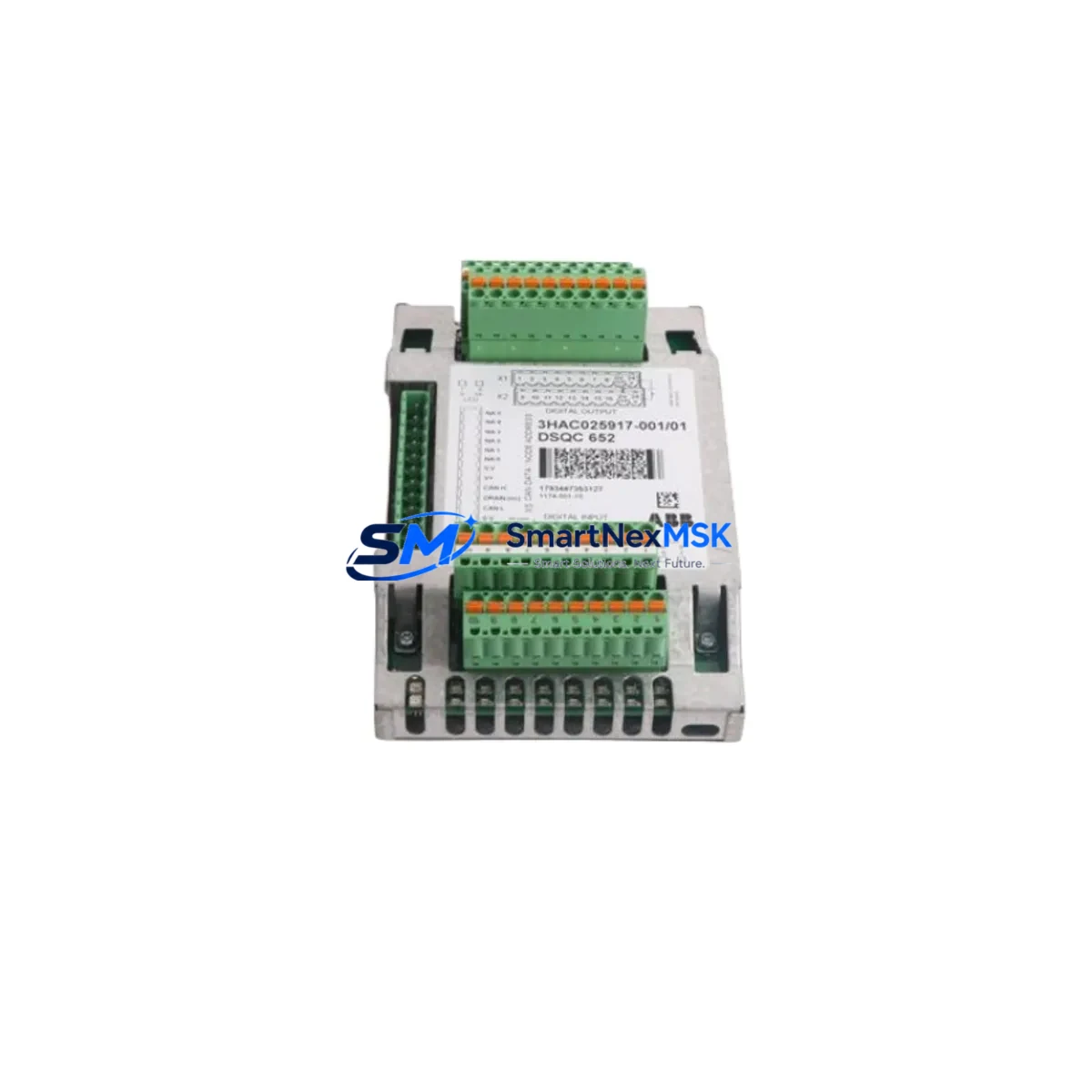
ABB TK812V015 Retrofit-Ready Analog Input for MOD 300 Systems: Compatible Modernization and Smooth Legacy Upgrade
The ABB TK812V015 is an 8-channel analog input module originally designed for the Advant MOD 300 Distributed Control System (DCS). As aging MOD 300 installations reach end-of-support milestones, plant engineers and automation integrators increasingly rely on verified retrofit-ready replacements to sustain production continuity without committing to full platform migrations. The TK812V015 addresses this need directly — providing a drop-in compatible solution for facilities operating legacy Advant control architectures across oil and gas, pulp and paper, chemical processing, and power generation sectors.
SMARTNEXMSK maintains verified stock of the TK812V015 with full pre-shipment functional testing, original firmware integrity checks, and a 12-month warranty covering hardware defects under normal operating conditions. Each unit is inspected against ABB’s original module specification before dispatch, ensuring that retrofit engineers receive a module ready for immediate rack installation and loop commissioning.
Upgrade Compatibility Table
| Parameter | TK812V015 Specification | Retrofit Notes |
|---|---|---|
| Module Type | 8-Channel Analog Input | Direct replacement for same-slot analog input positions in MOD 300 racks |
| Signal Range | 4–20 mA / 0–10 V (configurable) | Verify field wiring signal type before installation; no hardware jumper changes required for standard 4–20 mA loops |
| Backplane Interface | MOD 300 S800 I/O bus | Compatible with standard MOD 300 I/O subrack; confirm backplane connector seating torque per ABB installation guide |
| Module Address | Configured via DIP switch / software | Record existing module address from outgoing unit before removal; replicate on TK812V015 prior to rack insertion |
| Power Consumption | ≤ 3.5 W (typical) | Verify subrack power supply (e.g., SS823 or SS832 power supply modules) has sufficient headroom; total rack load must not exceed rated capacity |
| Communication Protocol | Advant Fieldbus / PROFIBUS DP (via coupler) | No protocol migration required for like-for-like replacement; PROFIBUS coupler modules (e.g., CI854A) remain unchanged |
| Terminal Wiring | Screw-terminal field connection unit (FCU) | Retain existing FCU and field wiring; only the module card is replaced — no re-termination required |
| Program Compatibility | Full compatibility with existing AC 800M / MOD 300 application programs | No application code changes required; channel scaling and tag assignments remain valid after hot-swap or cold replacement |
| HMI Integration | Compatible with Operate IT / IndustrialIT HMI | Existing HMI faceplates and trend displays remain functional; no graphic reconfiguration needed |
| Warranty | 12-Month Hardware Warranty | Covers manufacturing defects under normal operating conditions; includes pre-shipment functional test certificate |
Retrofit Planning for Existing Automation Systems
Successful TK812V015 retrofits begin well before the module arrives on site. A structured pre-replacement audit should document the existing rack layout, including the positions of all installed I/O modules, the subrack power supply configuration, and the current module address assignments. In a typical MOD 300 installation, the TK812V015 shares a subrack with other S800 I/O modules such as the TK851V007 digital output module, the TK852V007 digital input module, and the TK814V015 analog output module. Confirming that the subrack’s SS823 or SS832 power supply module can sustain the combined load after replacement is a mandatory pre-commissioning step.
For sites running PROFIBUS DP communication, the CI854A PROFIBUS DP coupler module acts as the communication gateway between the S800 I/O bus and the AC 800M controller. The TK812V015 replacement does not require any reconfiguration of the CI854A, provided the module address is preserved. Engineers should also verify that the TB820 media redundancy switch — if installed — remains correctly configured for the updated rack topology.
Field connection units (FCUs) are a critical element of the retrofit workflow. The TK812V015 uses a dedicated FCU that mates with the module’s backplane connector and provides screw-terminal access to field wiring. In most legacy installations, the FCU remains in place during module replacement, eliminating the need to disturb field wiring. This significantly reduces the risk of wiring errors and shortens the commissioning window. Engineers should inspect FCU terminal screws for corrosion and verify torque values before re-energizing the loop.
Where the retrofit involves migrating from an older TK811V015 or TK810V015 analog input variant, engineers must confirm that the channel count, signal range, and FCU type are compatible with the TK812V015. In most cases, the migration is straightforward, but sites using non-standard signal conditioning or intrinsic safety barriers should perform a full loop check on each channel after replacement. The AC 800M controller’s Control Builder M engineering tool can be used to force individual channel outputs during commissioning without interrupting the broader control program.
For installations that include an Operator Workplace (OWS) running Operate IT or IndustrialIT, the HMI faceplates associated with the replaced analog input channels will continue to display correctly after the TK812V015 is installed, as the tag database and channel assignments are preserved in the controller application. No HMI reconfiguration or graphic rebuild is required for a like-for-like module replacement.
Downtime Control During System Migration
Minimizing unplanned downtime is the primary operational concern during any DCS module replacement. For the TK812V015, the recommended approach is a planned maintenance window replacement rather than an emergency swap, allowing the control team to prepare a structured commissioning sequence in advance.
Before removing the outgoing module, the control engineer should place all affected analog input loops into manual mode at the AC 800M controller level, ensuring that downstream regulatory control loops — such as PID controllers relying on the affected input signals — are held at their last valid output. This prevents process upsets caused by signal loss during the module swap interval. The Control Builder M tool provides a live diagnostic view of module status, allowing the engineer to confirm that the replacement TK812V015 has been recognized by the controller and that all eight channels are reporting valid signal values before returning loops to automatic mode.
For critical process inputs where even brief signal interruption is unacceptable, a parallel measurement strategy using a temporary portable signal generator can be used to simulate the field signal during the swap window. This approach is particularly relevant for temperature or pressure inputs feeding safety-instrumented functions, where signal loss may trigger a protective shutdown. Coordination with the safety system engineer is recommended before proceeding with any replacement on safety-critical loops.
Post-replacement, a full channel-by-channel loop check should be performed and documented, confirming that each of the eight analog input channels on the TK812V015 is reading within the expected engineering unit range. Any channel offset or scaling discrepancy should be investigated before the module is returned to service. SMARTNEXMSK’s pre-shipment test certificate provides a baseline reference for expected channel performance, which can be compared against field commissioning readings to identify any installation-related issues.
Retrofit Support FAQ
Q1: Is the TK812V015 a direct drop-in replacement for the TK811V015 or TK810V015 in the same MOD 300 subrack?
In most configurations, yes. The TK812V015 uses the same backplane slot form factor and FCU interface as earlier TK81x analog input variants. However, engineers should verify the FCU part number and signal range configuration before installation, as some early MOD 300 installations used non-standard FCU variants. SMARTNEXMSK can provide a compatibility confirmation based on your existing module part number and subrack configuration.
Q2: What commissioning steps are required after installing the TK812V015?
After physical installation, confirm the module address matches the outgoing unit, verify that the controller has recognized the new module in Control Builder M, and perform a channel-by-channel loop check for all eight analog input channels. Place affected control loops in manual mode before the swap and return them to automatic only after all channels have been verified. No application code changes are required for a like-for-like replacement.
Q3: Does the TK812V015 require re-termination of field wiring?
No. The field connection unit (FCU) remains in place during module replacement, and all field wiring stays connected to the FCU terminals. Only the module card is removed and replaced. This eliminates re-termination risk and significantly reduces the commissioning window. Inspect FCU terminal screws for corrosion and verify torque before re-energizing.
Q4: What does the 12-month warranty cover, and is a test certificate included?
The 12-month warranty covers hardware defects arising under normal operating conditions, including component failures not attributable to installation error, overvoltage, or physical damage. Every TK812V015 shipped by SMARTNEXMSK includes a pre-shipment functional test certificate confirming that all eight channels were verified against ABB’s original module specification prior to dispatch. Warranty claims are processed directly through SMARTNEXMSK’s technical support team.
© 2026 SMARTNEXMSK. All rights reserved.
Original Source: https://smartnexmsk.com
Contact: [email protected] | +86 18259474341



