
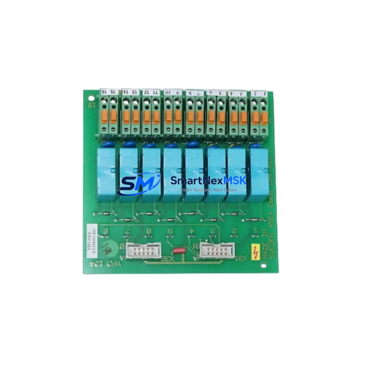
ABB YPO106A YT204001-EG Spare for INSUM Automation: Spare Replacement & Industrial Downtime Risk Control
The ABB YPO106A (catalog reference YT204001-EG) is an original digital output module designed for ABB’s INSUM (Intelligent Motor Control Unit) system — a distributed motor management and protection platform widely deployed in marine, offshore, and heavy industrial motor control centers (MCCs). When this module fails or degrades, the consequences extend beyond a single output channel: the entire INSUM node loses its ability to command downstream contactors, starters, and protection relays, triggering unplanned downtime in critical drive and motor circuits.
At SMARTNEXMSK, we stock the YPO106A as a maintenance-ready spare, fully tested before shipment, with a 12-month warranty and fast worldwide delivery. Whether you are executing a planned overhaul, responding to an emergency fault, or building a strategic spare parts buffer for aging INSUM installations, this module ships ready for immediate site installation.
Spare Maintenance Table
| Parameter | Specification / Detail |
|---|---|
| Part Number | YPO106A |
| Catalog / Order Code | YT204001-EG |
| Brand | ABB |
| Series | INSUM (Intelligent Motor Control Unit) |
| Module Type | Digital Output Module |
| Application | Motor Control Center (MCC), Marine & Industrial Automation |
| Output Channels | Digital relay/transistor outputs for contactor and starter command |
| Compatibility | ABB INSUM system nodes; drop-in replacement for existing YPO106A installations |
| Origin | Germany (ABB manufacturing) |
| Condition | Original, new or refurbished-to-spec; tested before shipment |
| Installation | DIN-rail or MCC backplane mount per INSUM system layout |
| Operating Environment | Industrial control cabinet; rated for marine and heavy industrial ambient conditions |
| Maintenance Recommendation | Replace proactively at first sign of output fault or communication loss; inspect relay contacts and wiring harness during replacement |
| Warranty | 12 Months — covers manufacturing defects and functional failure under normal operating conditions |
| Lead Time | In-stock items ship within 1–3 business days; express options available |
Maintenance Planning for Continuous Operation
Replacing the YPO106A in an INSUM node is rarely an isolated task. Maintenance engineers and procurement teams working on INSUM-based MCCs should treat this replacement as an opportunity to audit the surrounding electrical circuit and control architecture. A digital output module failure is frequently preceded or accompanied by degradation in adjacent components.
Begin with the INSUM communication module (typically the YCM110A or equivalent node controller): verify that the fieldbus link — whether PROFIBUS-DP or proprietary ABB protocol — is stable and that the node address is correctly assigned after the YPO106A swap. A corrupted node configuration can cause the new output module to appear faulty even when it is functioning correctly.
Inspect the 24 VDC auxiliary power supply feeding the INSUM node. Voltage sags or ripple on the control supply are a leading cause of premature digital output module failure. If the power supply is original to the installation and has not been replaced in the past five years, include an ABB CP series or equivalent 24 VDC DIN-rail PSU in your spare parts order alongside the YPO106A.
Check the digital input module (YPI series) on the same INSUM node. Input and output modules share the node backplane and power bus; a failing input module can generate spurious signals that stress output relay contacts. Confirm that all feedback signals from motor starters, auxiliary contacts, and thermal overload relays are reading correctly before closing the MCC door.
Review the motor protection relay associated with the controlled motor circuit — ABB SPAM150C, REF615, or equivalent. Ensure that trip and start commands from the YPO106A are correctly received and that relay settings have not drifted. This is also the right moment to verify contactor coil condition: a worn coil draws higher inrush current that can accelerate output relay contact wear on the YPO106A.
For installations with signal isolators between the INSUM output and field devices, inspect the isolator barrier for correct output voltage and isolation resistance. Degraded isolators can cause ground loops that corrupt digital output signals. Similarly, check terminal blocks and wiring harnesses on the output side: loose terminations and corroded ferrules are a common root cause of intermittent output faults that are incorrectly attributed to the module itself.
If the MCC includes an ABB Panel 800 or CP600 HMI for local motor status display, confirm that the HMI communication link to the INSUM gateway is restored after module replacement and that motor run/stop status is correctly reflected. Finally, for older installations, consider stocking a spare INSUM gateway module (YIG112 or equivalent) as part of your long-term obsolescence management strategy — gateway modules are increasingly difficult to source as INSUM installations age beyond 15–20 years.
Site Replacement Workflow
Step 1 — Isolation and lockout: Follow site LOTO procedures. De-energize the MCC section and verify absence of voltage on both the power and control circuits before opening the INSUM node enclosure.
Step 2 — Document existing configuration: Before removing the YPO106A, photograph or record the wiring harness connector positions, node address switches, and any DIP switch settings. INSUM modules use hardware addressing; incorrect address settings after replacement will cause node conflicts on the fieldbus.
Step 3 — Module extraction: Disconnect the wiring harness connector(s) from the YPO106A. Release the module retention clip and slide the module out of the backplane slot. Handle by the edges to avoid ESD damage to the PCB.
Step 4 — Incoming inspection: Verify the replacement YPO106A part number and catalog code (YT204001-EG) match the removed module. Check that node address switches are set identically to the original. Inspect the backplane connector pins for damage before insertion.
Step 5 — Installation and wiring: Seat the new module firmly into the backplane slot until the retention clip engages. Reconnect the wiring harness in the documented positions. Torque terminal screws to specification to ensure reliable contact.
Step 6 — Power-up and verification: Re-energize the control supply and observe the INSUM node status LEDs. Confirm that the YPO106A output LED indicators respond correctly to test commands from the INSUM gateway or HMI. Perform a functional test of each output channel before returning the motor circuit to service.
Step 7 — System restoration: Remove LOTO, restore MCC section to normal operation, and update the maintenance log with the replacement date, module serial number, and test results. Update your spare parts inventory to trigger reorder of a replacement YPO106A for the next maintenance cycle.
Spare Parts Support FAQ
Q1: Is the YPO106A (YT204001-EG) still available as a new original part, or only as refurbished?
We supply both new original and professionally refurbished-to-specification units depending on current stock. All units — regardless of condition — undergo full functional testing before shipment and are covered by our 12-month warranty. The condition is clearly stated on your order confirmation. If you require new original only, please specify at the time of inquiry.
Q2: How do I verify compatibility before ordering if my INSUM system uses an older firmware revision?
The YPO106A hardware is backward-compatible across INSUM system generations. Provide us with your INSUM gateway model number and node configuration, and our technical team will confirm compatibility before shipment. We recommend also sharing the existing module’s label photograph so we can match the hardware revision if multiple revisions exist in the field.
Q3: What is your lead time and shipping process for emergency breakdown orders?
In-stock units ship within 1–3 business days under standard terms. For emergency breakdown situations, contact us directly at [email protected] or +86 18259474341 to arrange priority processing and express freight. We ship worldwide and can provide DHL, FedEx, or UPS express options with tracking. All shipments include a test report and packing list.
Q4: What does the 12-month warranty cover, and what is the claim process?
The 12-month warranty covers manufacturing defects and functional failure under normal operating conditions from the date of shipment. It does not cover damage caused by incorrect installation, overvoltage, or physical impact. To initiate a warranty claim, contact [email protected] with your order number, a description of the fault, and photographs of the module and installation. We will arrange return shipping and replacement or repair within an agreed timeframe.
© 2026 SMARTNEXMSK. All rights reserved.
Original Source: https://smartnexmsk.com
Contact: [email protected] | +86 18259474341



