Allen-Bradley 1756-DNB Retrofit-Ready DeviceNet Scanner for ControlLogix Control Systems
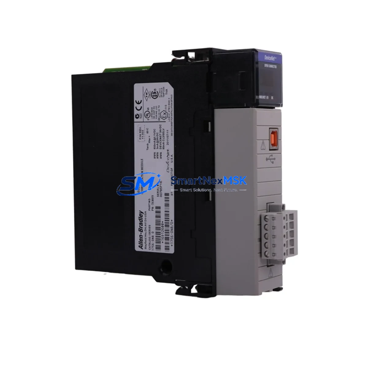
The Allen-Bradley 1756-DNB is a DeviceNet Scanner Module designed for the ControlLogix 1756 backplane platform. As legacy automation systems reach end-of-life or require capacity expansion, the 1756-DNB serves as a critical bridge between existing DeviceNet field device networks and modern ControlLogix controllers. Whether you are replacing a failed unit, upgrading a discontinued scanner, or migrating an entire control cabinet from an older SLC 500 or PLC-5 architecture, the 1756-DNB provides a verified, wiring-compatible retrofit path that minimizes engineering rework and reduces unplanned downtime.
This module occupies a single slot in any 1756 chassis — including the 1756-A4, 1756-A7, 1756-A10, and 1756-A13 rack sizes — and communicates directly with the ControlLogix controller via the ControlBus backplane. It supports up to 64 DeviceNet nodes per scanner instance, making it suitable for mid-to-large I/O networks involving distributed drives, sensors, valve manifolds, and operator panels connected over DeviceNet trunk cable.
Upgrade Compatibility Table
| Parameter | Details |
|---|---|
| SKU / Part Number | 1756-DNB |
| Platform | ControlLogix 1756 |
| Network Protocol | DeviceNet (CAN-based, ISO 11898) |
| Backplane Interface | ControlLogix 1756 ControlBus |
| Chassis Compatibility | 1756-A4, 1756-A7, 1756-A10, 1756-A13, 1756-A17 |
| Power Supply Compatibility | 1756-PA72, 1756-PB72, 1756-PA75, 1756-PB75 |
| Max DeviceNet Nodes | 64 nodes per scanner |
| Replacement for | 1771-SDN (PLC-5), 1747-SDN (SLC 500) |
| Programming Software | RSNetWorx for DeviceNet, Studio 5000 Logix Designer |
| Installation Slot | Any available 1756 chassis slot |
| Communication Baud Rate | 125 Kbps, 250 Kbps, 500 Kbps (auto-detect supported) |
| Warranty | 12-Month Warranty |
| Condition | New / Surplus New / Tested Refurbished |
| Shipping | Global express shipping, same-day dispatch available |
Retrofit Planning for Existing Automation Systems
When planning a retrofit involving the 1756-DNB, the first step is a thorough audit of the existing DeviceNet network topology. Engineers should document all node addresses currently assigned to field devices — including PowerFlex 40 and PowerFlex 700 variable frequency drives, 1734 POINT I/O adapter nodes, photoelectric sensors, and solenoid valve banks — before removing the legacy scanner. This node map becomes the reference for reconfiguring the replacement module in RSNetWorx for DeviceNet.
Power budget verification is equally critical. The 1756-DNB draws power from the 1756 chassis backplane, supplied by the installed 1756-PA72 or 1756-PB72 power supply. Before inserting the module, confirm that the chassis power supply has sufficient remaining capacity, particularly in high-density racks where multiple communication modules such as the 1756-ENBT Ethernet/IP bridge or 1756-CN2 ControlNet scanner may already be installed. Exceeding the backplane power budget will cause intermittent faults and unpredictable module behavior.
Terminal wiring on the DeviceNet trunk should be inspected and re-terminated if the cable has been in service for more than five years. The 1756-DNB uses a standard 5-pin open-style connector (V+, CAN_H, Shield, CAN_L, V−). Verify that the network termination resistors (121 Ω) are correctly placed at both physical ends of the trunk, and that drop cable lengths comply with DeviceNet specification limits for the selected baud rate. Incorrect termination is one of the most common causes of node communication errors after a scanner replacement.
For sites migrating from a PLC-5 platform using the 1771-SDN scanner or from an SLC 500 system using the 1747-SDN, the I/O mapping logic in the original ladder program must be re-mapped to ControlLogix tag-based addressing in Studio 5000 Logix Designer. The 1756-DNB uses explicit and polled messaging through the controller’s I/O tree, and each DeviceNet device must be re-commissioned with its EDS file loaded into RSNetWorx. Where HMI screens built on PanelView Plus terminals reference specific PLC-5 integer file addresses (N7, F8), those data references must be updated to reflect the new ControlLogix tag names to maintain display accuracy after cutover.
Downtime Control During System Migration
Minimizing production downtime during a DeviceNet scanner replacement requires a structured pre-commissioning approach. Before the scheduled maintenance window, prepare a complete offline backup of the existing controller program using Studio 5000 or RSLogix 5000, and export the RSNetWorx DeviceNet configuration file (.dnt) from the current system. These files serve as the recovery baseline if the cutover encounters unexpected issues.
During the physical swap, the 1756-DNB can be inserted into a powered chassis with the controller in Program mode, allowing the module to initialize without disrupting other I/O modules in the rack — including any 1756-IB16 digital input modules, 1756-OB16E digital output modules, or 1756-IF8 analog input modules that remain in service. Once the module is seated and recognized by the controller, import the saved RSNetWorx configuration and download it to the scanner. Verify that all 64 (or fewer) nodes return to the Run state before switching the controller back to Run mode.
For critical processes where even a brief interruption is unacceptable, consider staging a parallel rack with the 1756-DNB pre-configured and tested offline. This hot-swap preparation strategy — using a spare 1756-A7 chassis, a 1756-L73 controller in test mode, and a bench DeviceNet segment — allows full functional verification before the live cutover, reducing the on-site commissioning window to under 30 minutes in most cases.
Retrofit Support FAQ
Q: Is the 1756-DNB a direct drop-in replacement for the 1771-SDN used in PLC-5 systems?
A: The 1756-DNB is functionally equivalent in terms of DeviceNet scanning capability, but it is not physically interchangeable with the 1771-SDN. The 1771-SDN is designed for the 1771 I/O chassis used with PLC-5 controllers, while the 1756-DNB is designed for the ControlLogix 1756 backplane. A migration project will require chassis, power supply, and controller hardware changes in addition to the scanner module itself. Program logic must also be converted from RSLogix 5 ladder to Studio 5000 tag-based addressing.
Q: What wiring changes are required when replacing a failed 1756-DNB with a new unit?
A: The DeviceNet trunk connector is field-removable, so the existing 5-pin wiring harness can be transferred directly to the replacement module without re-terminating the trunk cable. After seating the new module, restore the RSNetWorx configuration from your saved .dnt backup file and verify node status before returning the system to Run mode. No changes to the controller program are required for a like-for-like replacement.
Q: How is compatibility verified before shipment?
A: Each 1756-DNB unit undergoes a functional bench test prior to dispatch. The test procedure includes backplane communication verification, DeviceNet port continuity check, firmware version confirmation, and a 24-hour power-on burn-in cycle. A test report is available upon request. All units are covered by a 12-month warranty from the date of shipment.
Q: Can the 1756-DNB coexist with Ethernet/IP and ControlNet modules in the same ControlLogix chassis?
A: Yes. The 1756-DNB communicates exclusively over the ControlLogix backplane and does not interfere with other communication modules such as the 1756-ENBT, 1756-EN2T, or 1756-CN2 installed in the same rack. Multiple communication protocols can operate simultaneously within a single ControlLogix chassis, subject to the chassis power supply capacity and slot availability.
© 2026 SMARTNEXMSK. All rights reserved.
Original Source: https://smartnexmsk.com
Contact: sales@smartnexmsk.com | +86 18259474341