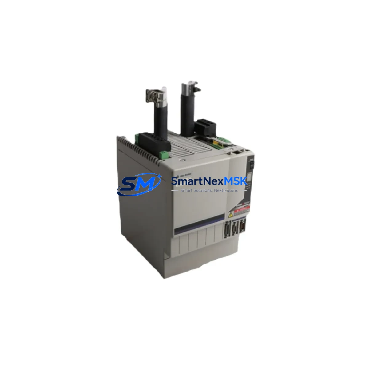
Allen-Bradley 2094-BC07-M05-M Spare for Kinetix 6000 Automation
The Allen-Bradley 2094-BC07-M05-M is an Integrated Axis Module (IAM) designed for the Kinetix 6000 multi-axis servo drive system. As a core power and control component within the Kinetix 6000 drive chassis, this IAM manages converter and inverter functions for the primary axis, making it a critical spare for any facility running Allen-Bradley servo-controlled machinery. Unplanned failure of this module can halt an entire production line. Maintaining a verified replacement unit on-site is the most effective strategy for minimizing unplanned downtime and accelerating fault recovery.
At SMARTNEXMSK, every 2094-BC07-M05-M unit is sourced from authorized supply channels, bench-tested prior to dispatch, and covered by a 12-month warranty. We support maintenance engineers and procurement teams with long-term spare parts availability, compatibility verification, and rapid order fulfillment.
Spare Maintenance Table
| Part Number | 2094-BC07-M05-M |
| Brand | Allen-Bradley (Rockwell Automation) |
| Series | Kinetix 6000 |
| Module Type | Integrated Axis Module (IAM) |
| Converter Input Voltage | 195–264 VAC, 3-phase |
| Continuous Output Current | 7 A RMS (inverter axis) |
| Bus Voltage | DC Bus shared across Kinetix 6000 chassis |
| Communication Interface | SERCOS fiber-optic ring (integrated) |
| Mounting | 2094-series power rail / drive chassis |
| Compatible Controllers | ControlLogix, CompactLogix (via 1756-M08SE / 1756-M16SE SERCOS interface) |
| Operating Temperature | 0–50 °C (derating above 40 °C) |
| Protection Rating | IP20 (panel-mount, control cabinet installation) |
| Certifications | UL, CE, cUL |
| Country of Origin | United States |
| Warranty | 12 Months — Tested & Verified Before Shipment |
| Maintenance Recommendation | Inspect DC bus capacitors, fiber-optic connectors, and cooling fan annually. Replace IAM if bus fault or overcurrent faults persist after drive reset. |
Maintenance Planning for Continuous Operation
When a 2094-BC07-M05-M IAM is flagged for replacement during a planned shutdown or emergency fault response, experienced maintenance engineers treat the event as a trigger for a broader control cabinet inspection. The IAM shares a DC bus with all Axis Modules (AM) installed on the same 2094-series power rail — modules such as the 2094-BMP5 and 2094-BM03-M — and a fault in the IAM can stress or mask faults in adjacent AMs. Each AM should be checked for overcurrent history and bus fault logs before the system is returned to service.
The SERCOS fiber-optic ring connecting the IAM to the ControlLogix controller via a 1756-M08SE or 1756-M16SE SERCOS interface module should be inspected for connector contamination, bend radius violations, and signal integrity. Degraded fiber links are a common source of intermittent axis faults that are misdiagnosed as IAM failures. Alongside the fiber ring, the 2090-series feedback cables and motor power cables connecting to the servo motors should be checked for insulation wear, connector corrosion, and continuity.
The 2094-BC07-M05-M draws its control power from the 2094-XL75S-C1 or equivalent Kinetix 6000 power supply module. If the IAM has failed due to an overvoltage or undervoltage event, the power supply module and its input line filter should be inspected and tested before the replacement IAM is energized. Installing a new IAM into a cabinet with an unresolved power quality issue risks immediate re-failure.
For facilities running mixed Allen-Bradley architectures, the upstream 1756-L7x or 1756-L8x ControlLogix CPU and its associated 1756-EN2T EtherNet/IP communication module should be confirmed as fault-free. SERCOS axis faults are sometimes triggered by controller task overruns or communication timeouts rather than drive hardware failures. Reviewing the controller’s fault log before committing to an IAM replacement can save significant labor time.
Additional components to inspect during a Kinetix 6000 IAM replacement event include: the 2094-series shunt module for regenerative load applications, terminal blocks and 24 VDC control wiring at the drive enable and fault reset inputs, and any safety relay or STO (Safe Torque Off) wiring connected to the drive’s safety inputs. Loose or corroded control wiring at these points is a frequent cause of nuisance faults that appear as drive hardware failures.
Site Replacement Workflow
Step 1 — Fault Isolation: Record all active and historical fault codes from the Logix Designer software before powering down. Distinguish between IAM-specific faults (converter, inverter, bus) and system-level faults (SERCOS ring, controller, feedback).
Step 2 — Safe De-energization: Follow Rockwell Automation lockout/tagout procedures. Verify DC bus voltage has discharged to safe levels (typically below 50 VDC) using a calibrated meter before opening the drive chassis.
Step 3 — Module Removal: Disconnect fiber-optic cables, motor power connectors, feedback connectors, and control wiring. Label all connections before removal. Slide the 2094-BC07-M05-M off the power rail.
Step 4 — Replacement Installation: Mount the replacement 2094-BC07-M05-M onto the power rail. Reconnect all cables in reverse order. Verify fiber-optic connectors are fully seated and lens surfaces are clean.
Step 5 — Configuration Restore: The Kinetix 6000 IAM stores axis parameters in the ControlLogix controller project, not in the drive module itself. No parameter re-entry is required — simply download the existing project to the controller and perform a drive commissioning test (autotune if motor parameters have changed).
Step 6 — Functional Verification: Run the axis through its full motion profile at reduced speed before returning to production. Monitor bus voltage, output current, and temperature via Logix Designer online monitoring for the first 30 minutes of operation.
This workflow minimizes downtime, preserves system compatibility, and ensures the replacement IAM is validated under real operating conditions before full production load is applied.
Spare Parts Support FAQ
Q1: Is the 2094-BC07-M05-M compatible with all Kinetix 6000 power rail configurations?
The 2094-BC07-M05-M is compatible with 2094-series power rails that support the BC07 converter rating. It must be used as the IAM (leftmost position) on the rail, not as an AM. Verify your rail catalog number and total axis count against Rockwell Automation’s Kinetix 6000 system sizing guide before installation.
Q2: How is the unit tested before shipment?
Every unit undergoes bench-level power-on testing, DC bus charge verification, and SERCOS communication initialization checks. Units that fail any test stage are quarantined and not shipped. A test report is available upon request for critical applications.
Q3: What is the recommended spare parts stocking strategy for Kinetix 6000 systems?
For production lines with more than four Kinetix 6000 axes, we recommend stocking at minimum one IAM (2094-BC07-M05-M or equivalent) and one AM of each current rating in use. Given that Kinetix 6000 is a mature product line with limited new production, securing long-term spare inventory now reduces exposure to future supply constraints.
Q4: What does the 12-month warranty cover?
The 12-month warranty covers defects in materials and workmanship under normal operating conditions. It includes free replacement or repair for units that fail during the warranty period due to verified product defects. Damage caused by incorrect installation, overvoltage events, or unauthorized modification is excluded. Warranty claims are processed within 5 business days of fault confirmation.
© 2026 SMARTNEXMSK. All rights reserved.
Original Source: https://smartnexmsk.com
Contact: sales@smartnexmsk.com | +86 18259474341