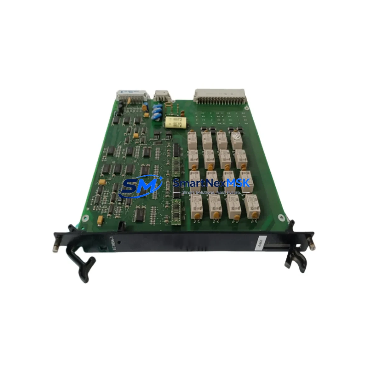
ALSTOM 232.2-5V 029.36 Retrofit-Ready Control Panel for ICP Series: Compatible Upgrade for Legacy Automation Systems
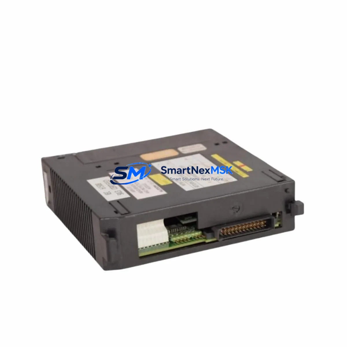
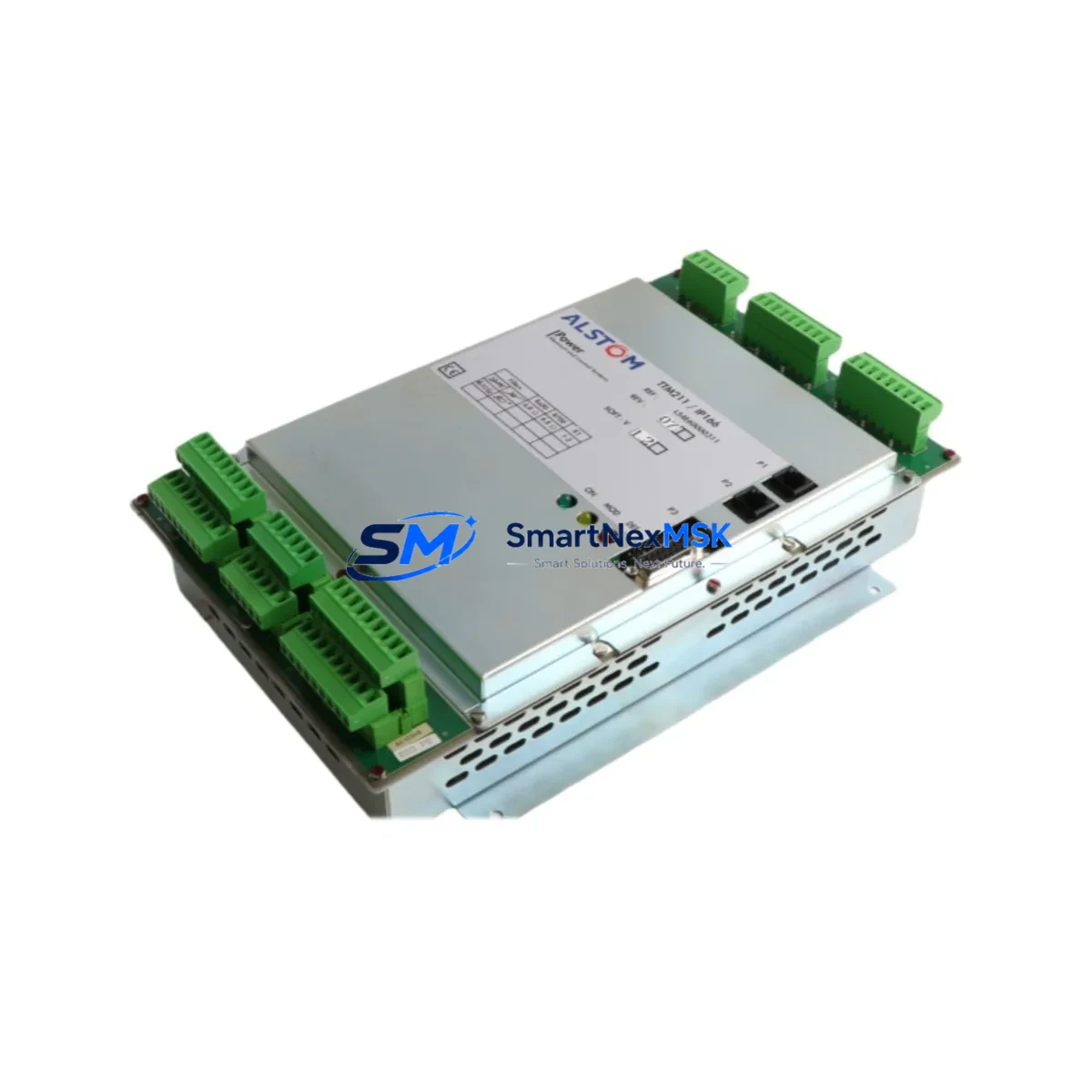
The ALSTOM 232.2-5V 029.36 is a retrofit-ready industrial control panel module engineered for seamless integration into ICP Series control systems. As legacy ALSTOM ICP platforms approach end-of-life and original spare parts become increasingly scarce, the 232.2-5V 029.36 provides a verified drop-in replacement path that preserves existing wiring infrastructure, backplane slot assignments, and program logic — minimizing both engineering rework and unplanned downtime.
This module is sourced from authorized distribution channels, individually tested prior to shipment, and backed by a 12-month warranty covering manufacturing defects and functional failures under normal operating conditions. Stock is maintained in Xiamen for rapid dispatch to global destinations, with typical lead times of 3–7 business days for standard orders.
Upgrade Compatibility Table
| Parameter | Details |
|---|---|
| SKU / Part Number | 232.2-5V 029.36 |
| Brand | ALSTOM |
| Compatible Series | ICP Series Control Systems |
| Mounting / Installation | DIN rail or panel-mount; backplane slot-compatible with ICP rack chassis |
| Supply Voltage | 5 VDC (as indicated by 5V designation) |
| Communication Compatibility | Compatible with ICP Series communication bus; verify protocol version with site engineer |
| Replacement Recommendation | Direct replacement for discontinued 232.2-5V variants; confirm terminal mapping before installation |
| Commissioning Notes | Verify module address configuration, I/O channel mapping, and HMI tag binding post-installation |
| Warranty | 12 months from date of shipment |
| Pre-shipment Testing | Full functional test performed on each unit |
Retrofit Planning for Existing Automation Systems
Successful integration of the ALSTOM 232.2-5V 029.36 into an existing ICP Series control cabinet begins with a thorough site survey. Engineers should document the current backplane layout, confirm available rack slots within the ICP chassis, and verify that the power supply module — typically an ALSTOM ICP PSU unit rated for the aggregate current draw of all installed modules — can support the addition or substitution without exceeding its rated capacity.
Terminal wiring should be mapped against the original I/O schedule before any physical disconnection. Where the legacy module used screw-terminal blocks, the replacement 232.2-5V 029.36 maintains the same terminal pitch, allowing existing field cables to be reconnected without re-crimping. For systems that include ALSTOM ICP analog input modules or digital output modules sharing the same rack, the module address (set via DIP switch or rotary selector depending on firmware revision) must be configured to match the address previously assigned to the removed unit to avoid address conflicts on the internal bus.
In control systems where the ICP Series communicates upstream to a SCADA or DCS via Modbus RTU, PROFIBUS DP, or a proprietary ALSTOM communication protocol, the communication link should be verified at the physical layer before re-energizing the panel. RS-485 termination resistors, baud rate settings, and station addresses on the communication module — often an ALSTOM ICP COM card installed in an adjacent slot — must remain unchanged to preserve data integrity with the host system.
For sites running ALSTOM’s proprietary programming environment or a third-party IEC 61131-3 compatible PLC programming tool, the existing application program does not require modification provided the replacement module presents the same I/O data structure to the controller. However, if the site has migrated to a newer ALSTOM controller platform or a third-party PLC such as a Schneider Electric Modicon or Siemens S7 series controller, a program adaptation may be required to remap I/O addresses. In such cases, the HMI screens — whether running on an ALSTOM operator panel or a third-party HMI terminal — should be reviewed to confirm that all tag references remain valid after the module swap.
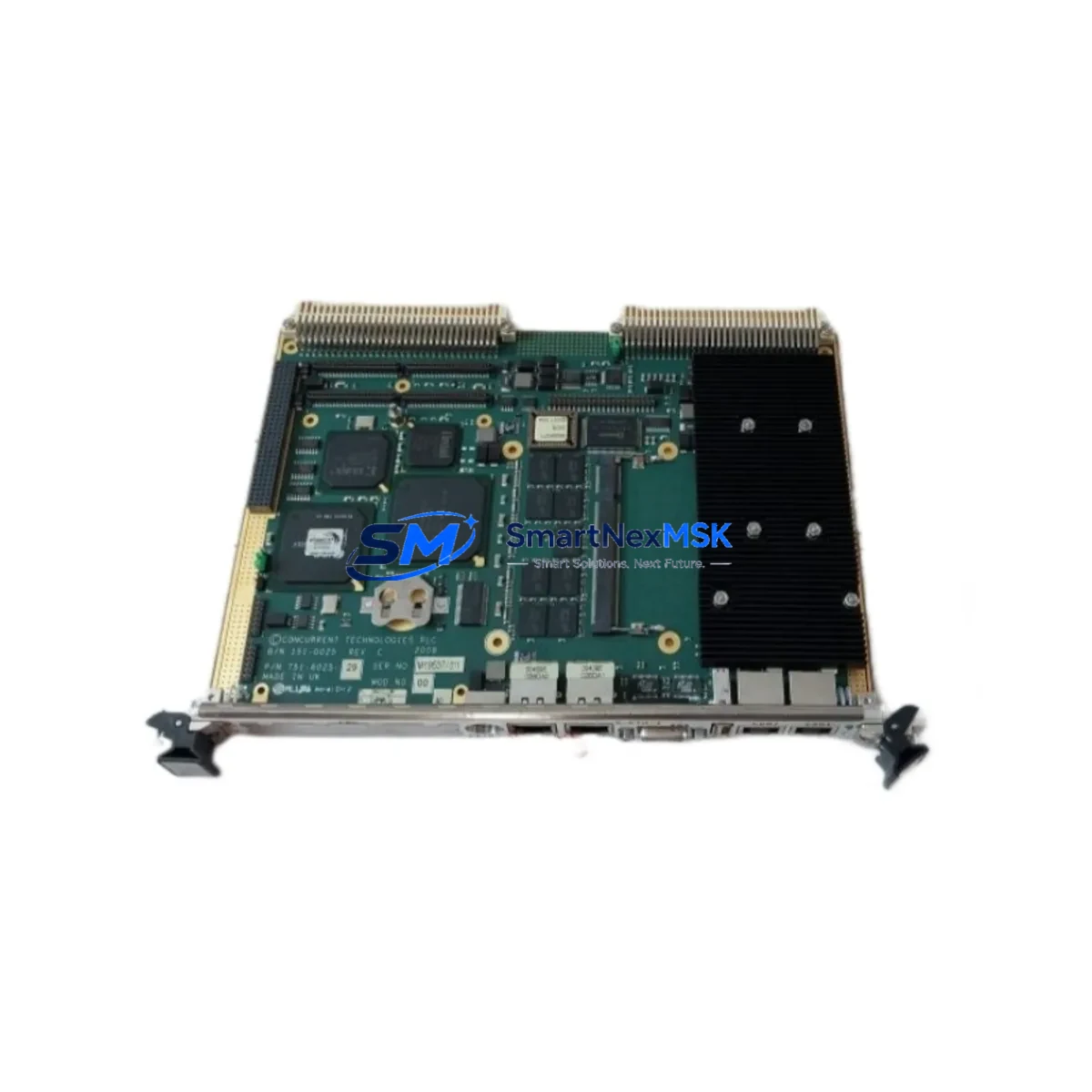
Where the retrofit involves expanding I/O capacity rather than a like-for-like replacement, additional ALSTOM ICP I/O expansion modules can be installed in adjacent rack positions. The system integrator should confirm that the ICP rack chassis has sufficient free slots and that the backplane bus bandwidth supports the additional I/O load. A full cold-start test of the control system, including simulation of all critical interlocks and alarm conditions, is recommended before returning the system to production.
Downtime Control During System Migration
Minimizing production interruption during a control panel retrofit requires careful pre-staging and a structured cutover plan. Before the scheduled maintenance window, the 232.2-5V 029.36 replacement module should be bench-tested with a representative I/O load to confirm correct operation. All configuration parameters — module address, I/O range settings, and communication parameters — should be pre-set to match the site configuration so that installation time is limited to physical mounting and terminal reconnection.
The existing application program should be backed up from the controller memory and stored on a secure engineering workstation before any hardware changes are made. If the ICP Series controller supports online program backup via its programming port or Ethernet interface, this should be performed immediately prior to the cutover to capture any recent program modifications. Where the controller does not support hot-swap of I/O modules, the affected I/O channels should be placed in a safe state — outputs de-energized, interlocks bypassed under permit-to-work — before the module is removed.
Following installation of the 232.2-5V 029.36, a structured commissioning sequence should be followed: power-on self-test, communication link verification, I/O channel-by-channel functional test, HMI display verification, and a supervised production trial run. Maintaining a detailed commissioning record — including as-found and as-left terminal readings, module firmware version, and test results — supports both quality assurance and future maintenance planning. With proper preparation, total cutover time for a single module replacement in an ICP Series panel is typically achievable within a two-to-four hour planned maintenance window.
Retrofit Support FAQ
Q1: Is the ALSTOM 232.2-5V 029.36 a direct drop-in replacement for the original ICP Series module?
A: In most ICP Series installations, the 232.2-5V 029.36 is a direct physical and functional replacement. Terminal pinout, backplane connector, and module dimensions are consistent with the original ICP Series specification. We recommend confirming the module address configuration and I/O channel mapping against your site documentation before installation.
Q2: What commissioning steps are required after installation?
A: After physical installation and terminal reconnection, verify the module address setting, confirm communication link status on the ICP bus, perform a channel-by-channel I/O functional test, and validate HMI tag bindings. A supervised trial run under normal operating conditions should be completed before returning the system to unattended operation.
Q3: Can this module be used in a system that has been partially upgraded to a newer controller platform?
A: The 232.2-5V 029.36 is designed for ICP Series backplane compatibility. In hybrid systems where the ICP rack is retained alongside a newer controller, compatibility depends on the communication interface between the ICP backplane and the new controller. Please contact our technical team with your system configuration details for a site-specific assessment.
Q4: What does the 12-month warranty cover, and how is it claimed?
A: The 12-month warranty covers manufacturing defects and functional failures under normal operating and storage conditions from the date of shipment. To initiate a warranty claim, contact sales@smartnexmsk.com with your order reference, a description of the fault, and photographic evidence of the defect. Replacement or repair will be arranged within 5 business days of claim approval.
© 2026 SMARTNEXMSK. All rights reserved.
Original Source: https://smartnexmsk.com
Contact: sales@smartnexmsk.com | +86 18259474341