Alstom 700.000 151/01 30 Retrofit-Ready Control Module for 700.000 Series: Seamless Compatibility and Legacy System Upgrade
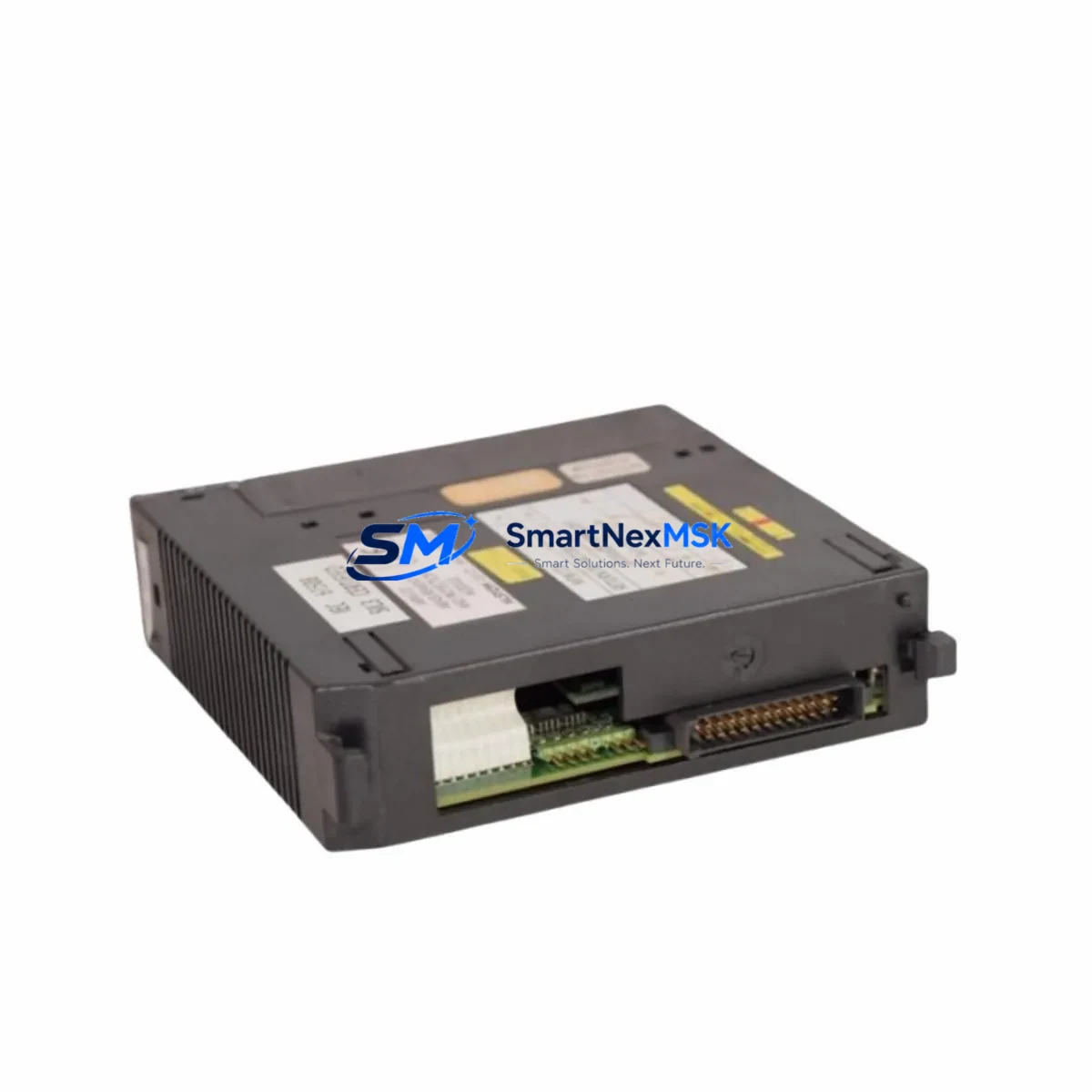
The Alstom 700.000 151/01 30 is a retrofit-ready control module engineered for direct replacement and smooth integration into existing 700.000 Series control systems. Whether you are managing a planned upgrade, responding to an end-of-life discontinuation notice, or recovering from an unplanned failure on a legacy production line, this module is designed to minimize engineering risk and reduce total downtime. With verified compatibility across the 700.000 Series platform architecture, the 700.000 151/01 30 supports engineers and procurement teams who need a reliable, in-stock solution backed by a 12-month warranty.
Industrial facilities running aging automation infrastructure face increasing pressure to source discontinued spare parts, validate drop-in replacements, and maintain control continuity without halting production. The 700.000 151/01 30 addresses these challenges directly — offering a tested, pre-shipment-verified module that integrates into the existing backplane, terminal wiring, and communication topology of the 700.000 Series without requiring full system redesign.
Upgrade Compatibility Table
| Parameter | Details |
|---|---|
| SKU / Part Number | 700.000 151/01 30 |
| Brand | Alstom |
| Series Compatibility | 700.000 Series Control Systems |
| Module Type | PLC Control Module |
| Backplane Interface | Compatible with 700.000 Series standard rack and backplane connectors |
| Terminal Wiring | Direct terminal-for-terminal replacement; no rewiring required under standard configurations |
| Communication Protocol | Compatible with existing 700.000 Series communication links (verify fieldbus version before installation) |
| Power Supply Requirement | Confirm rack power capacity before hot-swap; consult system power budget documentation |
| Module Address Configuration | Address switches or software-assigned; verify against original module configuration record |
| Program Compatibility | Existing PLC logic programs are retained; no recompilation required under standard firmware versions |
| HMI Screen Compatibility | Existing HMI tag mappings remain valid; verify after first power-on |
| Replacement Recommendation | Direct drop-in replacement for discontinued 700.000 151/01 30 units |
| Pre-Shipment Testing | Function-tested before dispatch |
| Warranty | 12 Months |
| Origin | China (CN) |
Retrofit Planning for Existing Automation Systems
Successful retrofit of the Alstom 700.000 151/01 30 into a live or recently decommissioned control system requires systematic pre-installation planning. Engineers should begin by auditing the existing rack configuration, confirming that the 700.000 Series backplane and rack chassis are structurally sound and that the power supply module — typically a dedicated 24VDC or 120/240VAC unit within the same control cabinet — can support the current draw of the replacement module alongside all co-installed I/O modules.
Terminal block wiring should be documented and photographed before removal of the original module. In most 700.000 Series installations, the terminal layout is standardized, allowing direct reconnection without modification. However, if the original installation included field-modified wiring or non-standard cable routing, a point-to-point continuity check is recommended before energizing the replacement unit.
Communication link integrity is a critical checkpoint. The 700.000 Series typically operates within a broader control architecture that may include a dedicated communications processor module, a remote I/O adapter, or a fieldbus gateway connecting to PROFIBUS, Modbus RTU, or proprietary Alstom communication protocols. Before commissioning the 700.000 151/01 30, verify that the communication cable — whether RS-485 shielded twisted pair or fiber optic — is properly terminated and that the network node address assigned to the replacement module matches the original configuration stored in the PLC program.
For systems that include digital input modules, analog output modules, or specialty function modules co-installed in the same rack, confirm that the module slot addressing has not shifted during the replacement process. Any change in slot assignment can cause I/O mapping errors that affect the PLC scan cycle and may trigger fault conditions on the HMI display. If the facility uses a SCADA system or DCS overlay connected to the 700.000 Series controller, notify the control room operator before initiating the swap and confirm that the communication link to the supervisory layer — often via an Ethernet gateway module or serial communications card — remains active throughout the procedure.
Programming cable access may be required during commissioning. Ensure that the appropriate programming interface — whether a USB-to-serial adapter, a dedicated PLC programming cable, or an Ethernet-based programming connection — is available on-site. After module installation, connect the programming terminal, verify that the CPU module recognizes the new 700.000 151/01 30, and perform a forced I/O test to confirm that all field devices respond correctly before returning the system to automatic mode.
Downtime Control During System Migration
Minimizing production downtime during a control module replacement requires advance preparation and a structured changeover sequence. Before scheduling the maintenance window, obtain the 700.000 151/01 30 replacement unit, verify its pre-shipment test documentation, and confirm that all required tools, wiring diagrams, and backup program files are staged at the work site.
Where the process allows, perform a controlled shutdown rather than an emergency stop. Save the current PLC program to an offline backup using the programming software, and record all current I/O force states, timer presets, and counter values. This ensures that if the replacement module requires any firmware-level initialization, the original program logic can be restored without relying on the controller’s internal memory alone.
During the physical swap, work systematically from the communication link disconnection through terminal block removal, module extraction, and replacement installation. Reconnect in reverse order. After power restoration, monitor the system status indicators on the module faceplate and confirm that the CPU module — and any co-installed specialty modules such as a PID loop controller or a high-speed counter module — return to normal operating status within the expected startup sequence.
If the system includes redundant control paths or a hot-standby configuration, coordinate the switchover with the standby controller before removing the primary module. This approach maintains field control continuity and prevents process upsets during the transition. Once the replacement 700.000 151/01 30 is confirmed operational, perform a full I/O scan, verify HMI tag values against field instrument readings, and document the completed retrofit in the facility’s maintenance management system.
Retrofit Support FAQ
Q1: Is the 700.000 151/01 30 a direct drop-in replacement for the original discontinued unit?
A: Yes. The 700.000 151/01 30 is designed as a direct replacement for the original Alstom 700.000 Series module of the same part number. It uses the same backplane connector, terminal layout, and module form factor. No mechanical modification to the rack or cabinet is required under standard installation conditions. Verify firmware version compatibility if your system is running a non-standard software revision.
Q2: What commissioning steps are required after installation?
A: After physical installation, connect the programming terminal and verify that the CPU recognizes the module. Perform a forced I/O test on all connected field devices. Confirm communication link status with any connected remote I/O or fieldbus network. Check HMI tag values against live field readings. If the module address was software-assigned on the original unit, re-enter the address configuration before returning the system to automatic mode.
Q3: How do I verify wiring compatibility before installation?
A: Compare the terminal block layout of the replacement 700.000 151/01 30 against the as-built wiring diagram for the original installation. In standard 700.000 Series configurations, terminal assignments are consistent across production batches. If the original wiring diagram is unavailable, perform a point-to-point continuity check from the field device terminals to the module connector before energizing.
Q4: What does the 12-month warranty cover, and what is the return process?
A: The 12-month warranty covers manufacturing defects and functional failures under normal operating conditions. Each unit is function-tested before shipment. If a warranty claim is required, contact sales@smartnexmsk.com with the order reference and a description of the fault. Replacement or repair will be arranged promptly. Warranty does not cover damage resulting from incorrect installation, overvoltage, or unauthorized modification.
© 2026 SMARTNEXMSK. All rights reserved.
Original Source: https://smartnexmsk.com
Contact: sales@smartnexmsk.com | +86 18259474341