AMCI 8213 Retrofit-Ready Programmable Limit Switch for PLS Series Control Systems
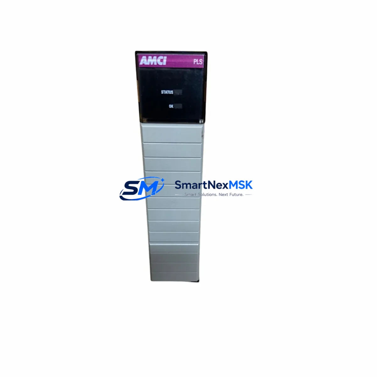
The AMCI 8213 is a retrofit-ready programmable limit switch (PLS) module engineered for seamless integration into existing PLS Series automation architectures. Whether you are replacing an end-of-life unit on a legacy packaging line, upgrading a motion-control cabinet, or migrating from an older cam-based limit switch system, the AMCI 8213 delivers the output resolution, timing accuracy, and electrical compatibility required to restore full system functionality with minimal downtime. Backed by a 12-month warranty and shipped only after full functional testing, the 8213 is a trusted choice for maintenance engineers and system integrators managing aging automation infrastructure.
Industrial facilities operating legacy rotary cam switches, older PLS controllers, or first-generation encoder-based limit systems frequently encounter obsolescence challenges: discontinued firmware, unavailable spare parts, and incompatible communication interfaces. The AMCI 8213 addresses these challenges directly. Its compact form factor and standard DIN-rail or panel-mount installation footprint allow it to occupy the same cabinet space as the unit it replaces, reducing the need for enclosure modifications. The module’s configurable output channels support both NPN and PNP logic, making it compatible with a wide range of PLC input cards from major automation platforms.
Upgrade Compatibility Table
| Parameter | Detail |
|---|---|
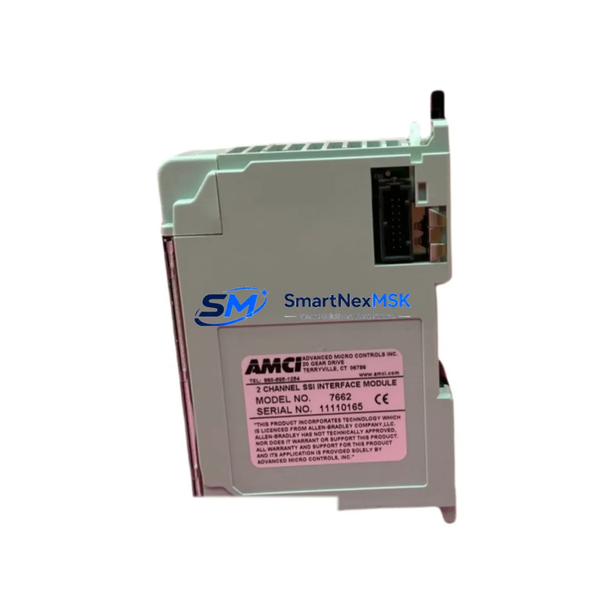
| SKU / Part Number | AMCI 8213 |
| Series | PLS Series (Programmable Limit Switch) |
| Typical Replacement For | Legacy cam-type limit switches, older AMCI PLS units, first-gen encoder-based controllers |
| Installation Type | DIN-rail or panel-mount; standard 35 mm DIN rail compatible |
| Output Configuration | Configurable NPN / PNP discrete outputs |
| Communication Compatibility | Compatible with standard PLC digital input modules; supports encoder feedback integration |
| Power Supply Requirement | Verify existing cabinet 24 VDC supply capacity before installation |
| Terminal Wiring | Screw-terminal block; verify existing wire gauge and labeling before swap |
| Backplane / Rack Interface | Standalone module; no backplane slot required |
| Module Address Setting | Confirm output channel addressing in PLC program before commissioning |
| Program Compatibility | Verify PLC ladder logic output references match new module channel mapping |
| HMI Screen Impact | Review HMI tag bindings for limit switch status indicators after replacement |
| Commissioning Requirement | On-site encoder calibration and output verification recommended |
| Warranty | 12 Months — full functional test performed prior to shipment |
| Stock Status | Available from inventory; global shipping supported |
Retrofit Planning for Existing Automation Systems
A successful AMCI 8213 retrofit begins well before the module arrives on-site. The first step is a thorough audit of the existing control cabinet. Engineers should document the current wiring scheme at the terminal block, confirm the 24 VDC power supply has sufficient current headroom to support the replacement module alongside other loads, and photograph the original installation for reference during reassembly. If the legacy system used a cam-type mechanical limit switch, the transition to the encoder-based AMCI 8213 will require mounting an incremental or absolute encoder — such as an AMCI encoder compatible with the 8213’s input interface — on the rotating shaft or cam follower.
In multi-axis or multi-zone systems, the 8213 often operates alongside other AMCI PLS modules, discrete I/O expansion modules, and dedicated motion controllers. When the control cabinet also houses a PLC — for example, a rack-mounted controller with analog and digital I/O cards — the output signals from the 8213 must be mapped correctly to the PLC’s input module terminals. Confirm that the existing PLC program references the correct input addresses before powering the system. If the original system used a different output polarity (NPN vs. PNP), update the PLC input card configuration or replace the input module accordingly.
Communication link integrity is equally important. In systems where the PLS data feeds an HMI panel for operator visualization of cam position or output status, verify that the HMI tag database reflects the new module’s output channel assignments. Any mismatch between the HMI screen tags and the actual PLC input addresses will cause false status displays and may trigger nuisance alarms. For systems using serial communication between the PLS and a supervisory controller, confirm baud rate, parity, and stop-bit settings match the host system’s expectations.
Where the retrofit involves replacing multiple modules simultaneously — for example, swapping out an entire PLS rack that includes power supply modules, encoder interface cards, and output relay modules — it is advisable to stage the replacement zone by zone rather than performing a full system cutover. This approach allows the maintenance team to validate each zone’s wiring and program logic independently, reducing the risk of a full-line shutdown caused by a single wiring error. Keep the original modules on-hand as reference units until the new installation has completed at least one full production cycle without fault.
Downtime Control During System Migration
Minimizing production downtime during a PLS module replacement requires a structured pre-outage preparation plan. Before the scheduled maintenance window, the engineering team should export and archive the current PLC program, including all rung comments and I/O force tables, to a secure backup location. If the system uses a programming cable — such as a USB-to-serial adapter or a dedicated PLC programming interface — confirm that the cable and software are available and functional before the outage begins. Attempting to locate programming tools during an unplanned outage significantly extends recovery time.
During the swap, work systematically through the terminal block, disconnecting and labeling each wire before removal. Use the pre-installation photographs and wiring diagrams as a reference. Once the AMCI 8213 is physically installed and wired, perform a cold-start power-up with the PLC in program mode — do not place the controller in run mode until all output channel assignments have been verified against the program logic. Use the PLC’s I/O status display or a handheld signal tester to confirm that each output channel activates at the correct encoder position before resuming production.
For systems where continuous control is critical — such as packaging lines, press brakes, or conveyor indexing systems — consider using a temporary bypass relay to maintain a safe-state output signal on critical channels while the module is being replaced. Document the bypass configuration and remove it immediately after the new module is commissioned. Retain all commissioning records, including encoder calibration values and output channel test results, as part of the equipment maintenance log. These records support future troubleshooting and provide evidence of due diligence for safety audits.
Retrofit Support FAQ
Q: Is the AMCI 8213 a direct drop-in replacement for my existing PLS module?
A: The 8213 is designed for PLS Series applications and shares the same functional role as legacy programmable limit switch modules in this family. However, terminal pinout, encoder input type, and output channel count should be verified against your existing wiring diagram before installation. Our technical team can assist with compatibility confirmation based on your current part number and wiring documentation.
Q: What wiring changes are typically required during installation?
A: In most retrofit scenarios, the existing 24 VDC power wiring and discrete output wiring can be reused. The primary wiring task is confirming that the encoder signal wires (A, B, Z channels and shield) are correctly terminated at the 8213’s input terminals. If the original system used a different encoder interface standard, an encoder signal conditioner may be required between the encoder and the module.
Q: How do I verify compatibility with my existing PLC program before installation?
A: Review the PLC program’s input rung references for the limit switch channels. Confirm that the I/O address assignments in the program match the physical terminal assignments on the 8213. If the original module used a different channel numbering scheme, update the program’s I/O mapping before going live. A full offline simulation using the PLC programming software is recommended before the maintenance window.
Q: What does the 12-month warranty cover, and what pre-shipment testing is performed?
A: Every AMCI 8213 unit is functionally tested prior to shipment, including encoder input signal verification, output channel activation at programmed positions, and power supply current draw measurement. The 12-month warranty covers manufacturing defects and functional failures under normal operating conditions. Units showing damage from incorrect wiring, overvoltage, or physical impact are not covered. Warranty claims are processed with return authorization; replacement units are dispatched promptly to minimize your system downtime.
© 2026 SMARTNEXMSK. All rights reserved.
Original Source: https://smartnexmsk.com
Contact: sales@smartnexmsk.com | +86 18259474341