AMCI SD3520 Maintenance-Ready Spare for SD Series Automation
The AMCI SD3520 is a high-performance stepper/servo indexer drive module engineered for demanding industrial automation environments. As a maintenance-ready original spare, the SD3520 is purpose-built to support rapid field replacement, minimize unplanned downtime, and sustain continuous operation in SD Series motion control systems. Whether you are managing a scheduled overhaul, responding to an emergency fault, or building a proactive spare parts inventory for a multi-axis control cabinet, the SD3520 delivers the electrical compatibility, firmware alignment, and mechanical form factor required for a drop-in replacement without system reconfiguration.
Maintenance engineers and procurement specialists working with AMCI SD Series platforms recognize the SD3520 as a critical node in stepper-driven positioning systems. Its integrated indexer logic eliminates the need for a separate motion controller in many single-axis applications, reducing cabinet complexity and the number of components that require periodic inspection. When the SD3520 is flagged during a fault diagnostic or routine point inspection, a verified spare on the shelf means the difference between a two-hour recovery and a multi-day production halt.
Spare Maintenance Table
| Parameter | Specification / Detail |
|---|---|
| Part Number / SKU | SD3520 |
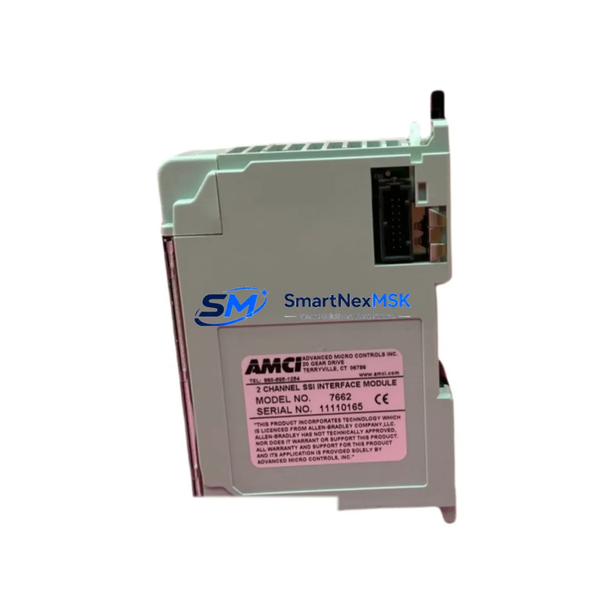
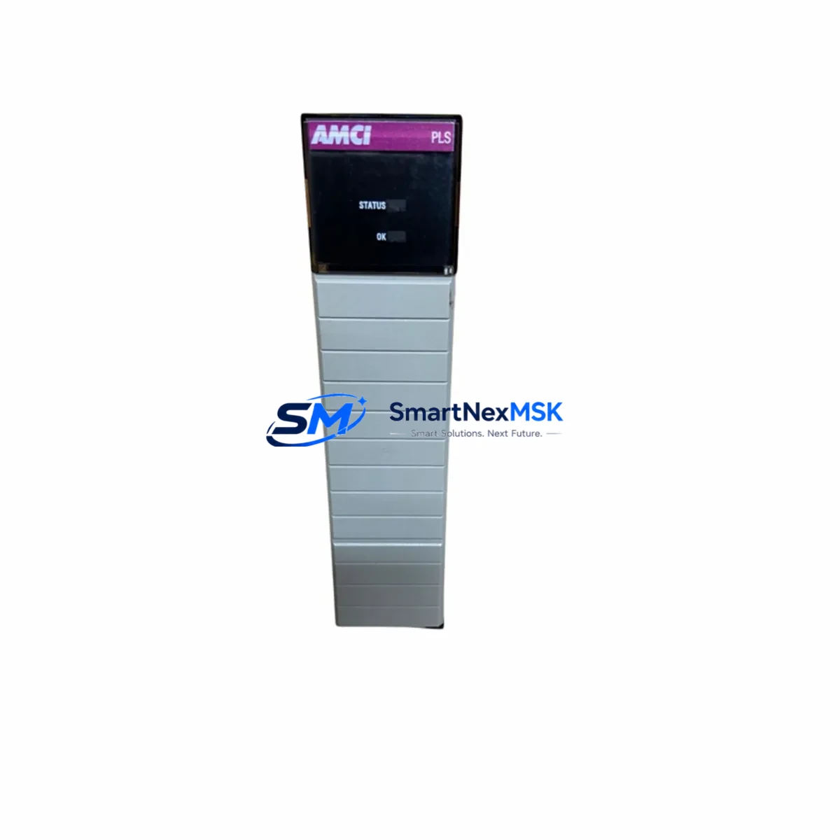
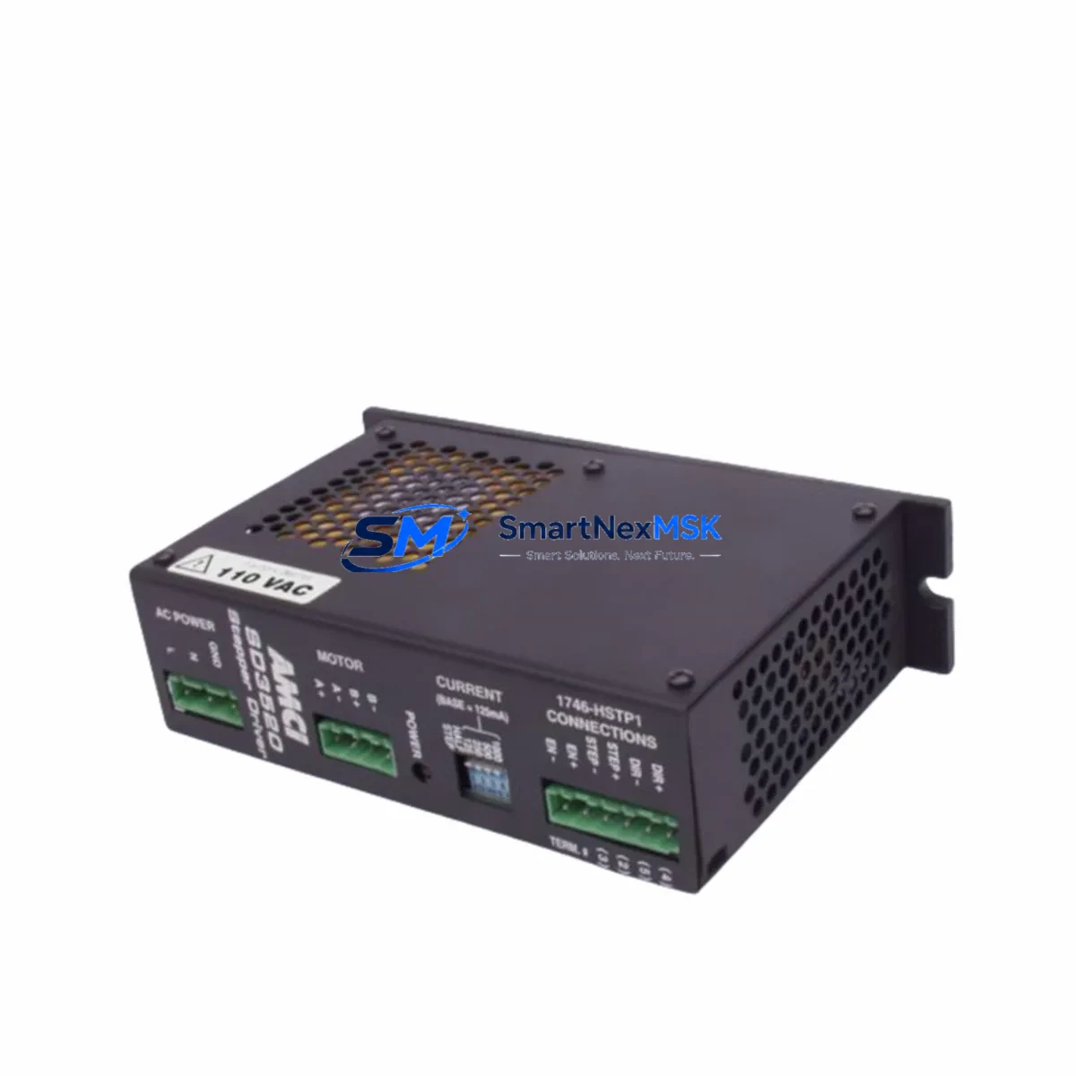
| Brand | AMCI (Advanced Micro Controls Inc.) |
| Series | SD Series Stepper/Servo Indexer Drive |
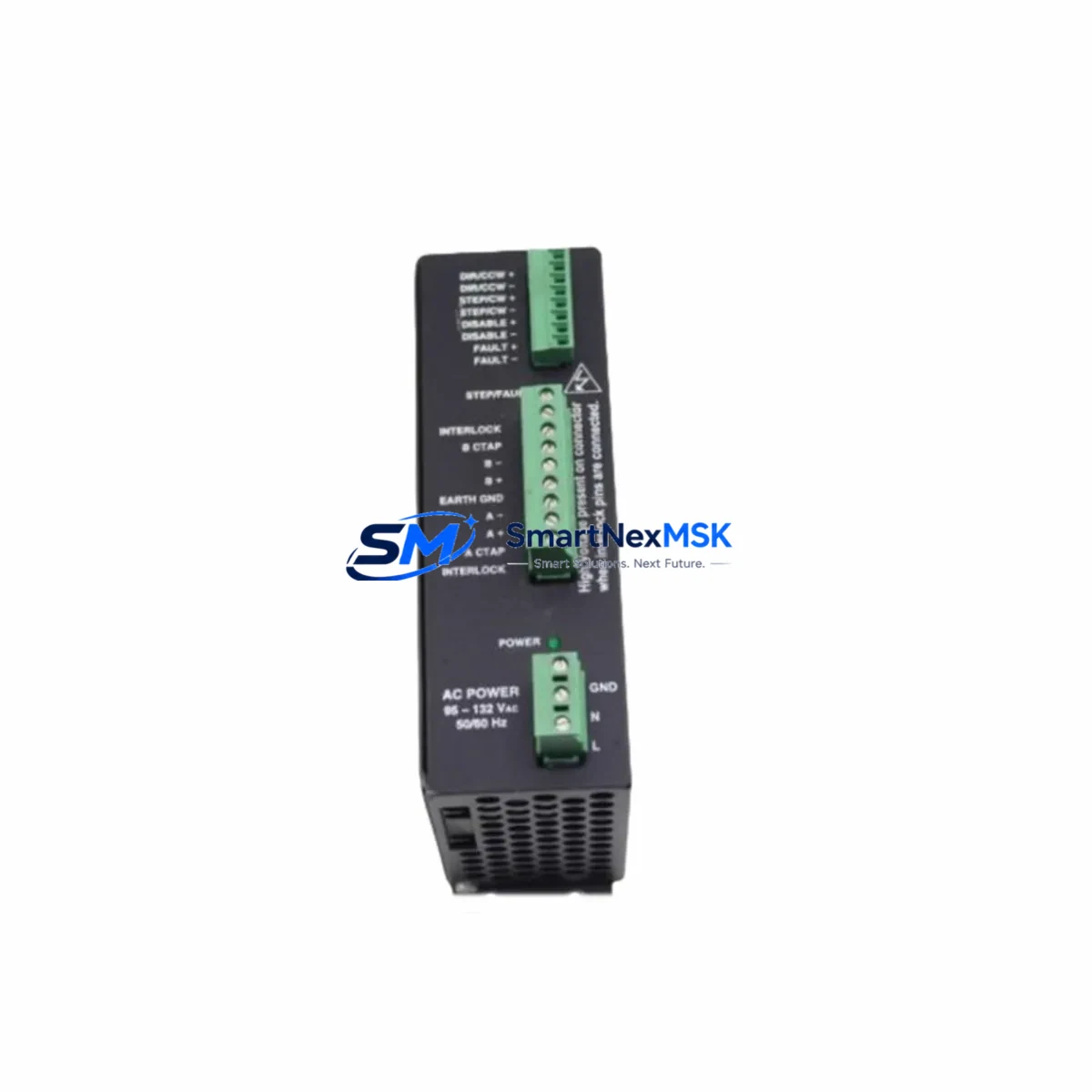
| Product Type | Stepper Servo Indexer Drive Module |
| Output Current | 3.5 A peak per phase (typical SD35xx class) |
| Supply Voltage | 24 VDC nominal (verify against system nameplate) |
| Indexer Interface | Integrated single-axis indexer; RS-422 / RS-485 serial or network-ready depending on variant |
| Motor Compatibility | 2-phase bipolar stepper motors; compatible with AMCI SD Series motor families |
| Mounting | DIN rail or panel mount; same footprint as SD3520 predecessor units |
| Operating Temperature | 0 °C to 50 °C ambient (standard industrial enclosure) |
| Protection Class | IP20 (control cabinet installation) |
| Origin | USA |
| Compatibility | Direct replacement for existing SD3520 installations; verify firmware revision with system integrator |
| Maintenance Recommendation | Inspect wiring harness, motor cable shield continuity, and 24 VDC supply rail at each replacement interval |
| Warranty | 12 Months — covers manufacturing defects; tested before shipment |
Maintenance Planning for Continuous Operation
A disciplined maintenance plan for any SD3520-equipped control cabinet extends well beyond the drive module itself. When a maintenance engineer isolates a fault to the SD3520, the replacement workflow should simultaneously trigger inspection of the surrounding electrical circuit to prevent repeat failures and confirm system integrity before restart.
Begin with the 24 VDC power supply module feeding the SD3520. Voltage sag, ripple, or intermittent dropout is a leading cause of indexer drive faults and can damage a replacement unit if left unaddressed. Verify output voltage under load and check capacitor health if the supply has accumulated significant operating hours. Next, inspect the motor power cable and encoder feedback cable — shielding integrity, connector seating, and insulation resistance are critical, particularly in environments with high vibration or frequent cable flexing.
The I/O interface wiring between the SD3520 and the host PLC or motion controller deserves careful attention. Loose terminals on the terminal block assembly or corroded contacts on the I/O connector can introduce intermittent faults that mimic drive failures. If the SD3520 communicates over a serial network, inspect the RS-422/RS-485 communication cable and termination resistors — a degraded network segment can cause command timeouts that trigger protective shutdowns.
For cabinets that also house AMCI NX Series network modules or AMCI 2-axis stepper controllers, confirm that the network topology and node addressing remain intact after the SD3520 swap. In multi-axis systems, replacing one drive without verifying the network configuration can cause axis conflicts or homing errors on adjacent axes.
Do not overlook the 24 VDC branch circuit fuse or circuit breaker protecting the SD3520 supply rail. A blown fuse is often a symptom of an upstream wiring fault rather than a drive failure; replacing the fuse without root-cause analysis risks damaging the new SD3520. Similarly, inspect any signal isolation modules or optocoupler I/O cards in the same cabinet — these components degrade over time and can introduce ground loops or signal noise that stress the indexer drive.
If the control system includes an HMI panel for operator interface, verify that the motion status registers and fault codes displayed on the HMI are cleared and re-initialized after the SD3520 replacement. Residual fault states in the HMI or PLC program can prevent the new drive from accepting commands. Finally, check the motor thermal overload relay or electronic overload protection in the motor branch circuit — an overload trip that was masked by the drive fault should be reset and its setpoint verified against the motor nameplate.
Site Replacement Workflow
Step 1 — Isolate and document. De-energize the control cabinet following your site LOTO procedure. Photograph the existing SD3520 wiring, DIP switch settings, and any jumper configurations before disconnection. This documentation is essential for restoring the replacement unit to the same operating parameters without referencing the original commissioning records.
Step 2 — Verify compatibility. Confirm that the replacement SD3520 matches the original unit’s firmware revision and hardware variant. AMCI periodically releases firmware updates that change default parameter behavior; if the replacement unit carries a different firmware version, consult the AMCI SD3520 user manual to identify any parameter differences before energizing.
Step 3 — Install and wire. Mount the replacement SD3520 on the DIN rail or panel using the same hardware as the original. Reconnect all wiring in the documented sequence — power supply, motor cable, I/O, and communication connections. Torque all terminal screws to specification to prevent loose connections under vibration.
Step 4 — Power-up and test. Energize the 24 VDC supply and verify that the SD3520 powers up without fault indicators. Command a low-speed jog move from the PLC or HMI to confirm motor response and direction. Verify position feedback and fault status registers before returning the axis to automatic mode.
Step 5 — Return to service and update records. Document the replacement date, unit serial number, and any parameter changes in the equipment maintenance log. Update the spare parts inventory to trigger reorder of a replacement SD3520 so the cabinet is never left without a verified spare on the shelf.
This workflow applies equally to planned maintenance replacements and emergency fault recovery scenarios. Maintaining a pre-tested SD3520 spare — verified for power-up and basic motion response before storage — reduces the on-site replacement time to under two hours in most installations.
Spare Parts Support FAQ
Q1: What is the warranty coverage for the SD3520 spare, and what does it include?
The SD3520 is supplied with a 12-month warranty covering manufacturing defects and component failures under normal operating conditions. Every unit is tested for power-up integrity and basic functional response before shipment. The warranty does not cover damage resulting from incorrect wiring, supply voltage outside the specified range, or physical mishandling during installation.
Q2: How do I verify that the replacement SD3520 is compatible with my existing system before installation?
Compatibility verification should include three checks: (1) confirm the SKU SD3520 matches the part number on the original unit’s nameplate; (2) compare the firmware revision label on the replacement unit against the original — if different, review the AMCI SD3520 release notes for parameter changes; (3) verify that the motor wiring configuration (current setting, microstep resolution, direction logic) matches your documented commissioning parameters. If you are replacing an older SD3520 that has been in service for more than five years, contact our technical team for a compatibility assessment before ordering.
Q3: Can I stock the SD3520 as a long-term spare, and what are the recommended storage conditions?
Yes. The SD3520 is suitable for long-term spare parts inventory. Store the unit in its original anti-static packaging in a dry environment between 0 °C and 40 °C with relative humidity below 85% non-condensing. Avoid storage near strong magnetic fields or high-vibration areas. For inventory programs exceeding 24 months, we recommend a periodic power-up test (annually) to verify capacitor health and confirm the unit remains fully functional before it is needed in the field.
Q4: What is the typical lead time, and do you offer pre-tested units for emergency dispatch?
Standard in-stock SD3520 units are dispatched within 1–3 business days. For emergency replacement requirements, contact sales@smartnexmsk.com or call +86 18259474341 to confirm real-time stock availability and expedited shipping options. All units shipped for emergency dispatch are pre-tested for power-up and basic motion response, with a test report available on request.
© 2026 SMARTNEXMSK. All rights reserved.
Original Source: https://smartnexmsk.com
Contact: sales@smartnexmsk.com | +86 18259474341