AMCI SD17060B-25 Retrofit-Ready Stepper Driver for SD Series Control Systems
The AMCI SD17060B-25 is a high-performance microstepping drive engineered for seamless integration into existing SD Series automation architectures. Whether you are replacing an end-of-life unit on a legacy production line, upgrading a control cabinet to meet current safety standards, or migrating from an older AMCI SD7540 or SD17040E drive, the SD17060B-25 delivers the electrical and mechanical compatibility your retrofit project demands — without requiring PLC program rewrites or panel redesign.
Designed for industrial environments where downtime is measured in lost revenue, this drive supports step-and-direction input signals compatible with Allen-Bradley Micro850, CompactLogix, and Siemens S7-1200 pulse output modules. Its 170 VAC input range and 6.0 A peak output current make it a direct functional replacement for earlier SD Series drives in single-axis and multi-axis stepper systems.
Upgrade Compatibility Table
| Parameter | SD17060B-25 (This Unit) | Typical Legacy SD Series |
|---|---|---|
| Input Voltage | 120–170 VAC, Single Phase | 120 VAC (older models) |
| Peak Output Current | 6.0 A | 4.0–5.0 A |
| Microstep Resolution | Up to 25,600 steps/rev | Up to 12,800 steps/rev |
| Step/Direction Interface | 5 V differential or single-ended | 5 V single-ended |
| Mounting | DIN rail / panel mount | Panel mount |
| Communication | RS-232 configuration port | DIP switch only |
| Replacement Recommendation | Direct drop-in for SD17040E, SD17060A | — |
| Commissioning Focus | Verify motor current, microstep setting, enable polarity | — |
| Warranty | 12 Months | Varies |
Retrofit Planning for Existing Automation Systems
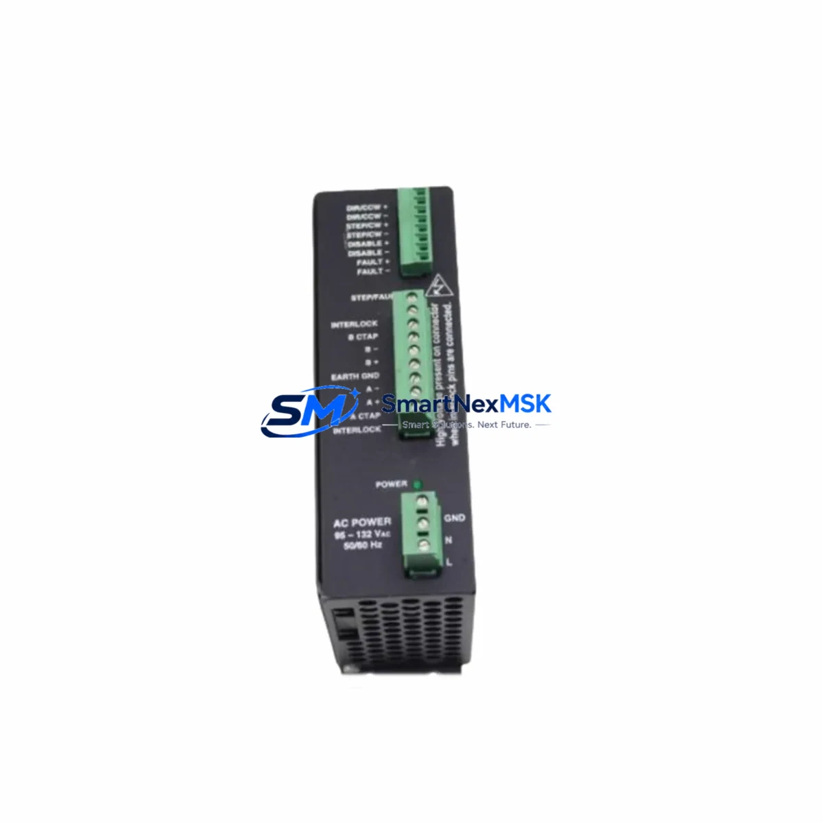
Successful retrofit of the SD17060B-25 into a running production environment requires a structured pre-installation audit. Begin by documenting the existing wiring from the PLC pulse output card — typically an AMCI ANX-PLS or equivalent step/direction output module — to the drive’s STEP+, STEP−, DIR+, and DIR− terminals. Confirm that the motor cable pinout matches the AMCI SD Series standard: Phase A, Phase A/, Phase B, Phase B/ on a 4-wire or 8-wire NEMA 23 or NEMA 34 frame motor.
If the control cabinet houses an AMCI ANG1E or ANG2E networked stepper indexer, verify that the indexer’s axis parameters — acceleration rate, deceleration rate, steps per unit, and home offset — are exported and backed up before the drive swap. These parameters reside in the indexer, not the drive, so they survive the replacement; however, confirming them before shutdown eliminates post-commissioning surprises.
For systems using an Allen-Bradley 1769-OB16 digital output module to generate step pulses, check the output frequency ceiling against the SD17060B-25’s maximum input frequency of 2 MHz. High-speed indexing applications may benefit from switching to a dedicated motion module such as the 1769-SM2 or an AMCI SMD23E2 networked drive to offload pulse generation from the PLC scan cycle.
Power supply sizing is critical. The SD17060B-25 draws up to 200 W at full load. If the existing 24 VDC control rail or AC distribution block is already near capacity — common in older panels housing multiple drives, an AMCI PS48 auxiliary power supply, and a 24 V SMPS for I/O — add a dedicated 15 A branch circuit for the drive’s AC input. Verify that the panel’s DIN rail ground bus is bonded to the machine frame to suppress EMI that can corrupt step pulses.
Where the legacy system used a Modbus RTU communication link to a SCADA or HMI panel — such as a Weintek MT8071iE or Proface GP4301TW — confirm that the HMI tag addresses for drive status, fault code, and position feedback remain valid after the swap. The SD17060B-25’s RS-232 port uses AMCI’s standard ASCII command set, which is backward-compatible with configurations written for the SD17060A.
Downtime Control During System Migration
Minimizing unplanned downtime during a stepper drive replacement begins with preparation, not speed. Before the maintenance window opens, pre-configure the SD17060B-25 on a bench using AMCI’s SD Configuration Utility: set motor current to match the nameplate rating of the installed motor, select the microstep resolution that matches the existing PLC motion profile, and confirm enable-input polarity. Save the configuration file so it can be reloaded in under two minutes if the drive is ever replaced again.
During the swap, label every wire before disconnecting the old drive. Use a continuity tester to verify terminal-to-terminal correspondence before applying power. After wiring, perform a low-speed jog — typically 10% of maximum velocity — to confirm correct motor rotation direction and absence of fault codes. Only then restore the axis to automatic mode and release the machine to production.
Keeping a spare SD17060B-25 pre-configured and on the shelf reduces mean time to repair (MTTR) from hours to minutes. Our stock is tested, serialized, and ships with a 12-month warranty covering manufacturing defects and premature failure under rated operating conditions.
Retrofit Support FAQ
Q: Is the SD17060B-25 a direct replacement for the SD17060A?
A: Yes. The SD17060B-25 is the current production successor to the SD17060A. Terminal layout, motor connector pinout, and step/direction signal levels are identical. The primary differences are the addition of an RS-232 configuration port and an increased microstep resolution ceiling. No PLC program changes are required.
Q: What wiring changes are needed when replacing an SD17040E with the SD17060B-25?
A: The SD17040E and SD17060B-25 share the same terminal block layout for step, direction, enable, and motor phase connections. The SD17060B-25 supports a higher peak current, so verify that the motor’s rated current does not exceed 6.0 A and adjust the current setting accordingly. No other wiring changes are required.
Q: How do I verify compatibility with my existing NEMA 23 stepper motor?
A: Confirm the motor’s phase current rating (must be ≤ 6.0 A), winding inductance (recommended 1–10 mH for optimal performance at your operating speed), and frame size. The SD17060B-25 is compatible with all standard 4-wire and 8-wire NEMA 23 and NEMA 34 motors used in SD Series applications.
Q: What does the 12-month warranty cover?
A: The warranty covers manufacturing defects and component failure under rated operating conditions for 12 months from the date of shipment. It does not cover damage from incorrect wiring, overvoltage, or operation outside the specified ambient temperature range (0–40 °C). Warranty claims are processed with return shipping provided at our cost.
© 2026 SMARTNEXMSK. All rights reserved.
Original Source: https://smartnexmsk.com
Contact: sales@smartnexmsk.com | +86 18259474341