Beckhoff BK3120 Maintenance-Ready Spare BK Series Automation
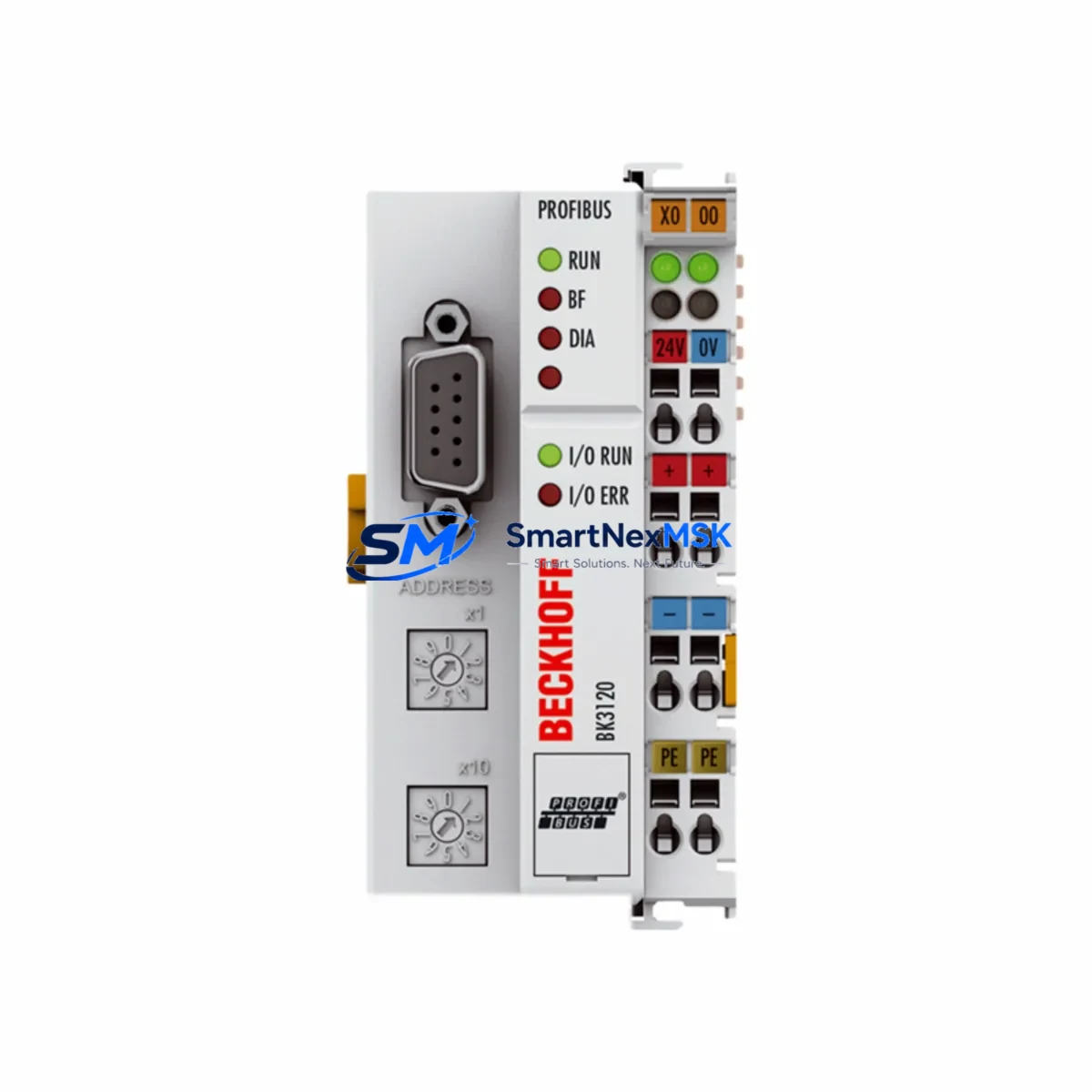
The Beckhoff BK3120 is a PROFIBUS DP Bus Coupler designed for the BK Series K-Bus system, serving as the critical gateway between the PROFIBUS DP fieldbus network and Beckhoff’s modular K-Bus I/O terminals. In industrial automation environments — from automotive assembly lines to process control panels — the BK3120 handles real-time data exchange between the PLC master and distributed I/O nodes. When this coupler fails or degrades, the entire I/O segment goes offline, triggering unplanned downtime that can cost thousands per hour in production loss.
Sourced as an original Beckhoff component, every BK3120 unit offered by SMARTNEXMSK undergoes pre-shipment functional verification. We maintain buffer stock specifically to support emergency replacement scenarios, planned maintenance windows, and long-term spare parts programs for facilities running legacy BK Series architectures.
Spare Maintenance Table
| Parameter | Specification |
|---|---|
| SKU / Part Number | BK3120 |
| Brand | Beckhoff |
| Series | BK Series (K-Bus) |
| Product Type | PROFIBUS DP Bus Coupler |
| Fieldbus Protocol | PROFIBUS DP (EN 50170) |
| Baud Rate | 9.6 kBaud – 12 MBaud (auto-detect) |
| Max. K-Bus Terminals | 64 terminals per coupler |
| Power Supply Voltage | 24 V DC (via power terminal) |
| Current Consumption (K-Bus) | ≤ 500 mA |
| Operating Temperature | 0°C to +55°C |
| Protection Rating | IP20 |
| Mounting | DIN rail (EN 60715) |
| Origin | Germany |
| Compatibility | Beckhoff BK Series K-Bus I/O terminals; PROFIBUS DP master controllers |
| Replaces / Compatible With | BK3100, BK3110, BK3150 (same K-Bus architecture) |
| Pre-Shipment Test | Yes — functional verification performed |
| Warranty | 12 Months |
Maintenance Planning for Continuous Operation
When a BK3120 Bus Coupler is flagged for replacement during a scheduled maintenance cycle or emergency fault isolation, experienced maintenance engineers know that the coupler itself is rarely the only component requiring attention. A thorough site inspection should extend to the surrounding electrical circuit and control cabinet to prevent repeat failures and ensure full system restoration.
Start with the 24 V DC power supply rail feeding the BK3120 and its K-Bus terminal strip. Voltage sags or ripple on this rail are a leading cause of coupler resets and communication faults. Verify the power terminal — typically a KL9100 or KL9010 end terminal — is properly seated and making clean contact. Inspect the KL9200 power feed terminal if the segment uses segmented power distribution.
Next, audit the K-Bus I/O terminals connected downstream of the BK3120. Terminals such as the KL1408 digital input, KL2408 digital output, and KL3202 PT100 analog input should be checked for secure DIN rail seating, intact K-Bus connectors, and correct address configuration. A single misaligned terminal can prevent the entire segment from initializing after coupler replacement.
For systems with mixed signal types, inspect any KL3001 or KL3002 analog input terminals and associated signal isolators in the circuit. Aging isolation barriers can introduce ground loops that stress the coupler’s communication interface. If the cabinet includes KL6001 or KL6021 serial communication terminals, verify their configuration parameters are retained after the coupler swap — these are often reset to factory defaults when the coupler is replaced.
On the PROFIBUS side, check the PROFIBUS DP cable termination resistors at both ends of the segment. Improper termination is a frequent cause of intermittent communication errors that are misdiagnosed as coupler failure. Also inspect the DB9 PROFIBUS connector on the BK3120 for pin corrosion or loose cable shielding.
If the control system includes a Beckhoff CX series Embedded PC or a third-party PROFIBUS master such as a Siemens S7-300/400 CP module, confirm that the GSD file and station address configuration match the replacement BK3120 before going live. Address conflicts will prevent the coupler from being recognized by the master.
For cabinets with protective devices, inspect the 24 V DC fuse or circuit breaker protecting the coupler power feed. A nuisance trip on this fuse is often the first symptom of an impending coupler failure. Replacing the fuse without addressing the root cause will result in repeat downtime. Finally, if the segment includes any KL9210 or KL9260 power supply terminals with diagnostic capability, review their status LEDs and error registers before closing the cabinet.
Site Replacement Workflow
Step 1 — Pre-replacement documentation: Record the current PROFIBUS station address set on the BK3120 rotary switches (typically two hex switches on the front face). Photograph the terminal strip layout and note the number and types of K-Bus terminals installed. Export or back up the PLC configuration if the master controller supports GSD-based auto-configuration.
Step 2 — Safe isolation: Place the PROFIBUS master in STOP mode or isolate the affected DP segment using the master’s configuration tool. De-energize the 24 V DC supply to the coupler segment. Do not remove the coupler under live power — K-Bus connectors are not hot-swap rated on the BK3120.
Step 3 — Physical replacement: Slide the BK3120 off the DIN rail by releasing the DIN rail latch. The K-Bus terminals will remain on the rail. Install the replacement BK3120, ensuring the K-Bus connector on the left side of the coupler engages fully with the first terminal. Set the PROFIBUS station address rotary switches to match the recorded values.
Step 4 — Power-up and verification: Re-energize the 24 V DC supply. Observe the BK3120 status LEDs: the RUN LED should illuminate green within a few seconds of the PROFIBUS master entering RUN mode. The I/O LED should cycle through initialization and settle green once all K-Bus terminals are recognized. If the ERR LED remains active, check terminal count, address setting, and PROFIBUS cable termination.
Step 5 — Functional test: Force test each I/O channel from the PLC or engineering workstation to confirm all terminals are responding correctly. Document the replacement in the maintenance log with the date, technician name, and new unit serial number.
This workflow minimizes mean time to repair (MTTR) and ensures the replacement BK3120 is fully validated before the system returns to production — reducing the risk of a second unplanned outage.
Spare Parts Support FAQ
Q1: Is the BK3120 still in production, and can I source it for long-term sparing?
The BK3120 is a mature Beckhoff product. While Beckhoff has introduced newer fieldbus coupler generations, the BK3120 remains in active use across thousands of installed PROFIBUS DP systems globally. SMARTNEXMSK maintains stock of original BK3120 units to support long-term spare parts programs for facilities that cannot migrate to newer architectures in the short term. Contact us to discuss multi-unit blanket orders or consignment stocking arrangements.
Q2: How is the BK3120 tested before shipment?
Each unit undergoes a functional power-on test confirming K-Bus initialization, PROFIBUS DP communication readiness, and LED status behavior. Units that fail any stage of this test are quarantined and not shipped. A test report is available upon request for quality-critical procurement processes.
Q3: What is covered under the 12-month warranty?
The 12-month warranty covers manufacturing defects and functional failures under normal operating conditions. It does not cover damage resulting from incorrect installation, overvoltage events, or environmental exposure beyond the rated IP20 / 0–55°C specification. Warranty claims are processed with a replacement unit dispatched upon receipt and inspection of the returned part.
Q4: Can the BK3120 replace a BK3100 or BK3110 in an existing installation?
The BK3120, BK3100, and BK3110 share the same K-Bus mechanical and electrical interface, making physical substitution straightforward. The key difference is the supported PROFIBUS baud rate range — the BK3120 supports auto-baud detection up to 12 MBaud. Verify that the replacement unit’s GSD file is loaded in the PROFIBUS master configuration before commissioning. In most cases, the existing GSD file for the BK3100/BK3110 will function correctly with the BK3120, but formal validation is recommended for safety-critical applications.
© 2026 SMARTNEXMSK. All rights reserved.
Original Source: https://smartnexmsk.com
Contact: sales@smartnexmsk.com | +86 18259474341