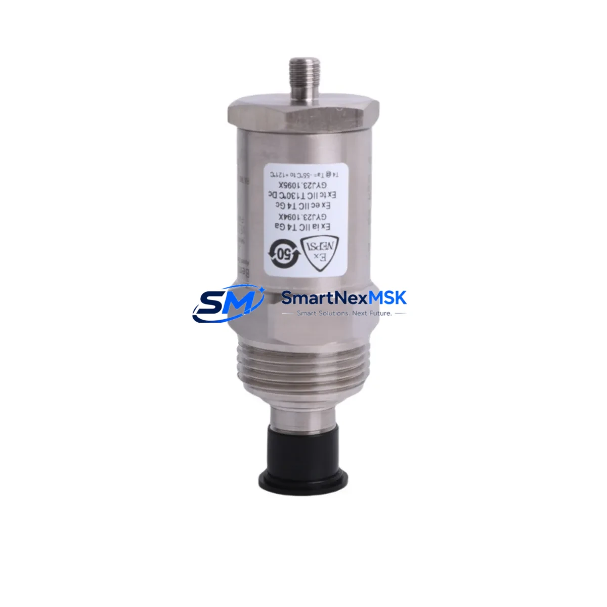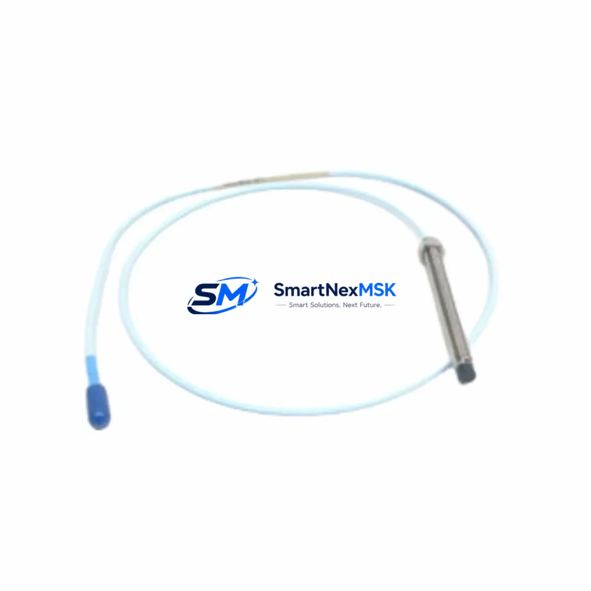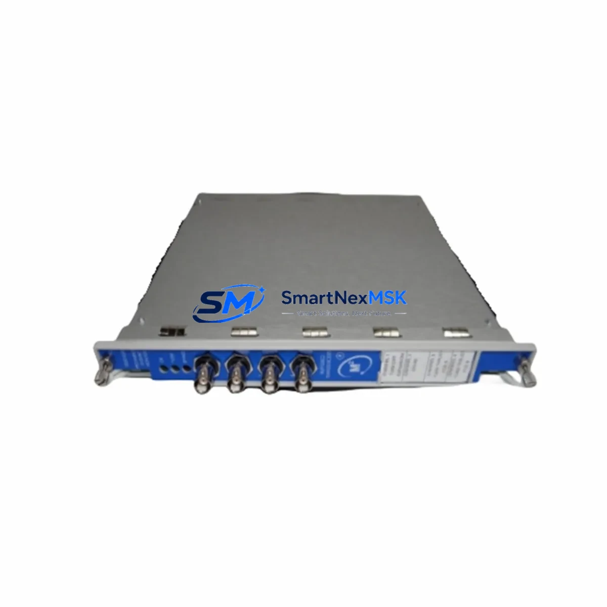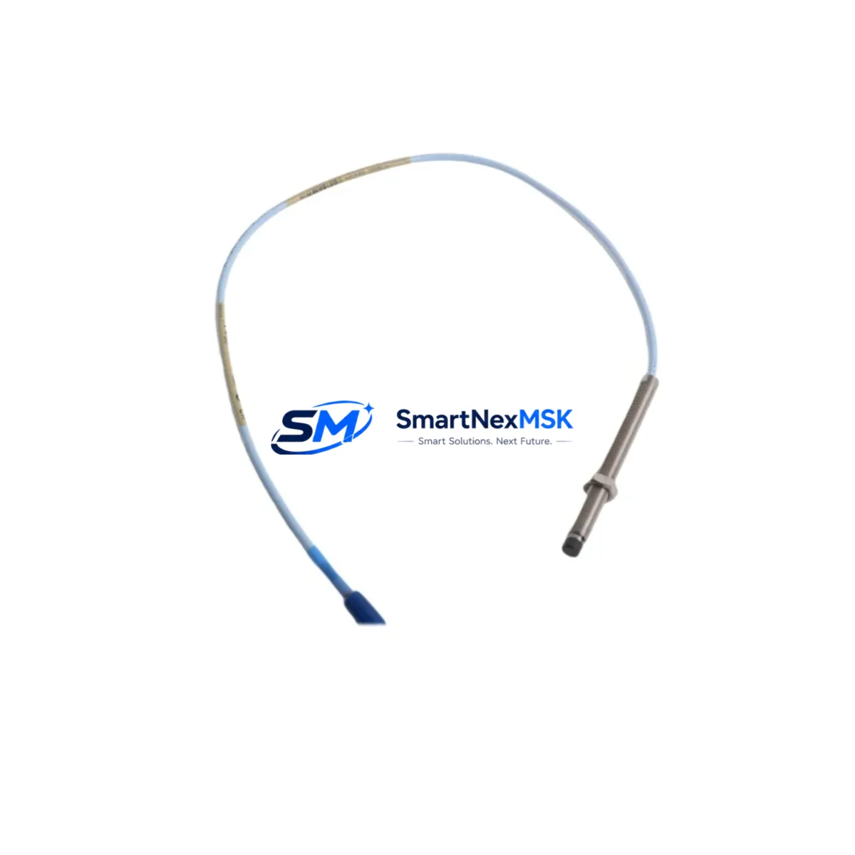
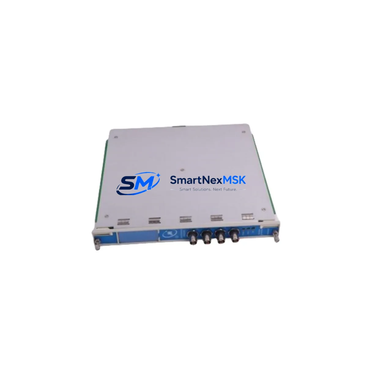
Bently Nevada 3500/54M Spare for 3500 Series Automation
The Bently Nevada 3500/54M (P/N 286566-01) is an original overspeed detection module designed for the Bently Nevada 3500 Series machinery protection system — one of the most widely deployed condition monitoring platforms in rotating equipment applications including turbines, compressors, pumps, and generators. For maintenance engineers managing critical rotating machinery, an unplanned overspeed trip or a failed detection module can result in extended downtime, production loss, and potential equipment damage. Stocking a verified replacement 3500/54M is a fundamental element of any serious spare parts strategy for facilities running 3500 Series racks.
This module monitors shaft speed signals and provides overspeed protection by continuously comparing measured speed against configured trip setpoints. When the 3500/54M fails or degrades, the entire overspeed protection channel is compromised — a condition that most safety-critical facilities cannot tolerate for more than a few hours. Our 3500/54M units are sourced as original Bently Nevada hardware, functionally tested prior to shipment, and backed by a 12-month warranty covering both parts and workmanship.
Spare Maintenance Table
| Parameter | Specification |
|---|---|
| Part Number | 286566-01 |
| Model | 3500/54M |
| Brand | Bently Nevada |
| Series | 3500 Series Machinery Protection System |
| Module Type | Overspeed Detection Module |
| Speed Inputs | Up to 3 independent speed sensor inputs |
| Trip Relay Output | Dedicated overspeed trip relay, configurable setpoints |
| Communication | 3500 Series backplane bus compatible |
| Power Supply | Supplied via 3500 Series rack backplane (3500/05 or 3500/15) |
| Operating Temperature | 0°C to 65°C |
| Mounting | 3500 Series rack slot (standard module form factor) |
| Compatibility | 3500/05 Rack, 3500/15 Rack, 3500/92 Communication Gateway |
| Application | Turbines, compressors, pumps, generators, rotating machinery |
| Condition | Original, functionally tested before shipment |
| Warranty | 12 Months — parts and workmanship |
Maintenance Planning for Continuous Operation
When a 3500/54M overspeed detection module is flagged for replacement during a planned outage or emergency shutdown, experienced maintenance engineers know that the module itself is rarely the only component requiring attention. A thorough inspection of the surrounding 3500 Series rack and associated field wiring is essential to ensure the replacement module performs reliably from the moment it is commissioned.
Begin by inspecting the 3500/05 Rack Power Supply or 3500/15 Rack backplane power rails. A degraded power supply can cause intermittent module faults that are misdiagnosed as module failures — replacing the 3500/54M without addressing a marginal power supply will result in repeat failures. Check the 3500/25 Enhanced Keyphasor Module as well: the Keyphasor signal is the timing reference for speed measurement, and a worn or contaminated Keyphasor probe or its associated cable can produce erratic speed readings that trigger nuisance trips or mask genuine overspeed conditions.
Inspect the speed sensor field wiring and connectors feeding the 3500/54M inputs. Proximity probe cables, extension cables, and 3300 XL 8mm proximity transducer assemblies are common wear items in high-vibration environments. Damaged cable shielding or loose connector terminations introduce noise into the speed signal chain and should be replaced as part of the same maintenance window. The 3500/92 Communication Gateway Module should also be verified — it handles Modbus or Ethernet communication between the 3500 rack and the plant DCS or historian, and a failed gateway can prevent alarm and trip data from reaching the control room even when the protection system itself is functioning correctly.
For facilities using the 3500/22M Transient Data Interface or 3500/42M Proximitor/Seismic Monitor in the same rack, confirm that these modules are communicating correctly on the backplane after the 3500/54M is replaced. Backplane connector pins can oxidize over time, particularly in humid or chemically aggressive environments, and a module swap is an ideal opportunity to clean and inspect all rack connectors. Additionally, review the configuration stored in the Rack Configuration Software (RCS) to confirm that trip setpoints, time delays, and relay logic for the 3500/54M are correctly loaded and match the as-built documentation for the machine train.
Procurement engineers should note that the 3500/54M is a long-lifecycle module but is subject to Bently Nevada’s product lifecycle management. Facilities with multiple 3500 racks protecting critical machinery trains should consider holding at least one spare 3500/54M per site, alongside spares for the 3500/05 Power Supply and the Keyphasor module, to ensure that any single-module failure can be resolved within a single shift without waiting for emergency procurement.
Site Replacement Workflow
Step 1 — Pre-replacement verification: Confirm the replacement 3500/54M (P/N 286566-01) matches the installed module’s part number and firmware revision. Review the rack configuration file in RCS to document current setpoints before any hardware is disturbed.
Step 2 — Safe isolation: Coordinate with the control room to place the overspeed protection channel in bypass or inhibit mode per site safety procedures. Do not remove the module while the machine is running unless the site’s safety management plan explicitly permits hot-swap under bypass.
Step 3 — Module removal and inspection: Remove the 3500/54M by releasing the front-panel locking mechanism. Inspect the backplane connector on both the module and the rack slot for bent pins, corrosion, or debris. Clean with appropriate contact cleaner if required.
Step 4 — Installation and configuration: Insert the replacement 3500/54M and secure the locking mechanism. Power up the rack and use RCS to download the verified configuration file to the new module. Confirm that all setpoints, relay assignments, and communication parameters are correctly applied.
Step 5 — Functional verification: Perform a speed signal injection test or use the rack’s built-in self-test function to verify that the module responds correctly to simulated overspeed conditions. Confirm that trip relays operate at the configured setpoints and that alarm and trip status is correctly reported to the DCS or historian via the 3500/92 gateway.
Step 6 — Return to service: Remove the bypass/inhibit, confirm normal operation, and update the maintenance record with the replacement date, new module serial number, and test results. Retain the removed module for evaluation — many 3500/54M modules can be repaired or recertified if the fault is limited to a single component.
Spare Parts Support FAQ
Q: Is the 3500/54M 286566-01 compatible with all 3500 Series rack configurations?
A: The 3500/54M is designed for use in the standard 3500 Series rack (3500/05 or 3500/15). It occupies a standard module slot and communicates via the 3500 backplane bus. Compatibility with specific rack configurations, firmware revisions, and RCS software versions should be confirmed against your as-built documentation before installation. Our technical team can assist with compatibility verification prior to shipment.
Q: How is the 3500/54M tested before shipment?
A: Each unit undergoes functional testing that includes power-up verification, backplane communication check, speed input signal response, and trip relay output confirmation. A test report is available upon request. Units that do not pass all test criteria are not shipped.
Q: What is the warranty coverage and what does it include?
A: All 3500/54M units are covered by a 12-month warranty from the date of shipment. The warranty covers defects in materials and workmanship under normal operating conditions. It does not cover damage resulting from incorrect installation, overvoltage, or physical impact. Warranty claims are processed with priority turnaround to minimize site downtime.
Q: Can you support long-term or blanket spare parts orders for multiple 3500 Series modules?
A: Yes. We support long-term supply agreements for facilities managing multiple 3500 Series racks. Blanket orders for the 3500/54M and associated modules such as the 3500/05 Power Supply, 3500/25 Keyphasor Module, and 3500/92 Communication Gateway can be arranged with agreed lead times and pricing. Contact our sales team to discuss your site’s spare parts inventory requirements.
© 2026 SMARTNEXMSK. All rights reserved.
Original Source: https://smartnexmsk.com
Contact: [email protected] | +86 18259474341