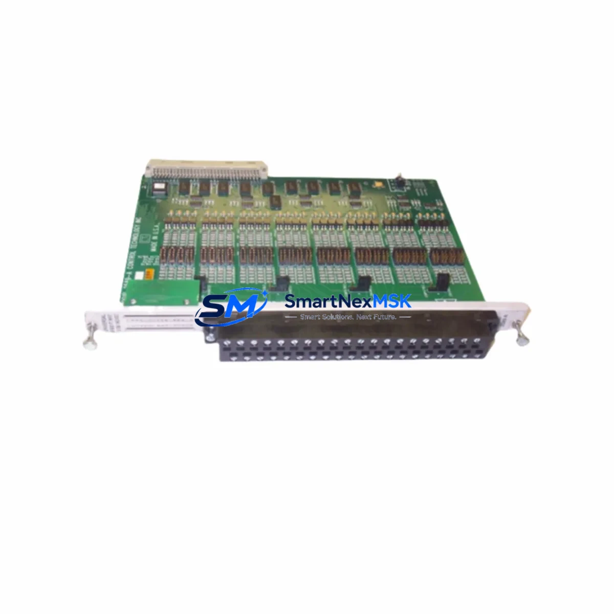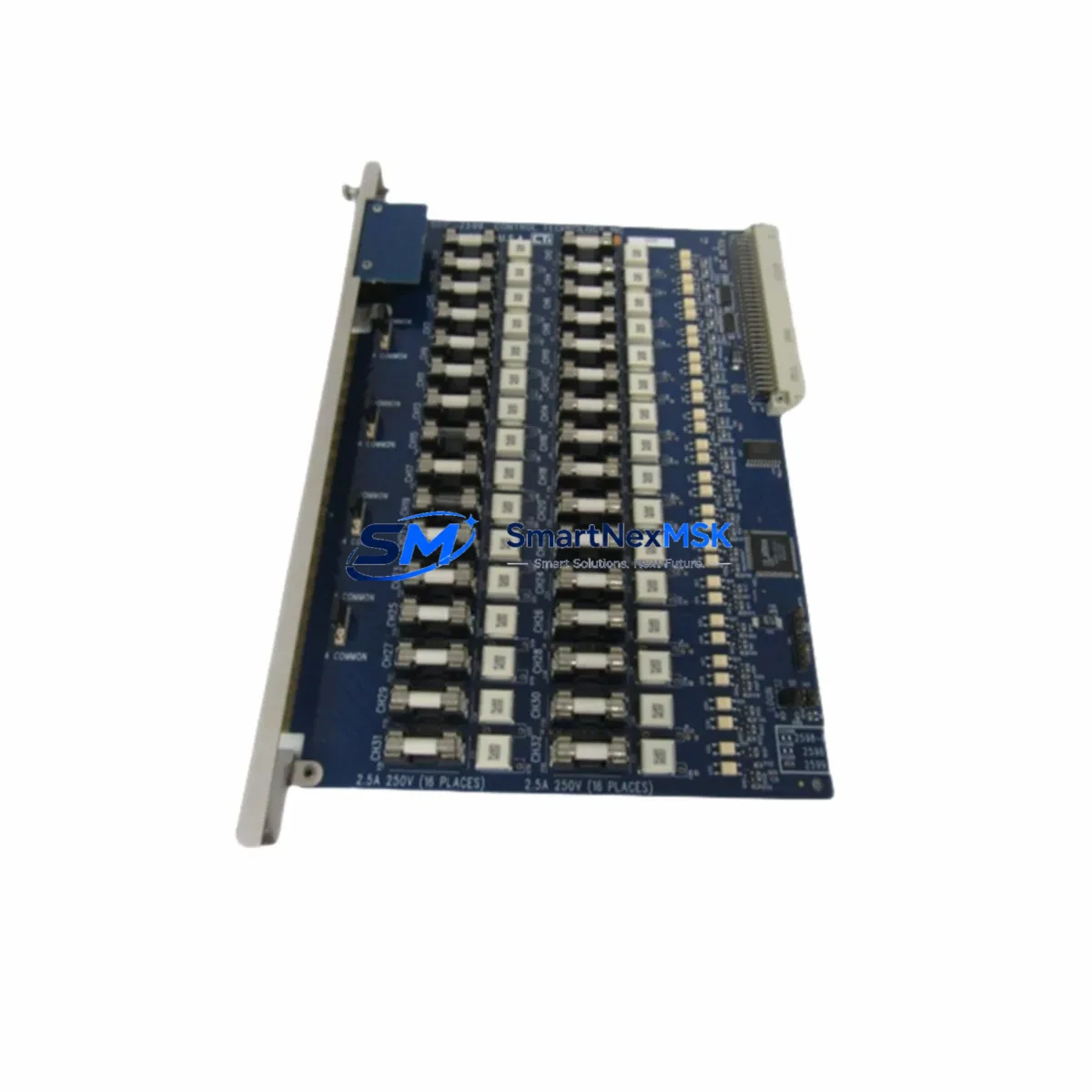
CTI 901C-2599 Maintenance-Ready Spare for 90-30 Automation
When a discrete output module fails in a Series 90-30 PLC rack, every minute of unplanned downtime translates directly into production loss, safety risk, and costly recovery procedures. The CTI 901C-2599 is an original-specification discrete output module engineered to restore control system integrity with minimal intervention. Designed as a direct maintenance replacement for aging or failed output modules in CTI 900 Series and GE Series 90-30 compatible racks, this module allows maintenance engineers to execute a clean swap, verify output continuity, and return the line to full operation — often within a single shift window.
For maintenance planners and procurement engineers managing aging PLC infrastructure, the 901C-2599 represents a reliable, cost-effective alternative to full system upgrades. Its compatibility with standard Series 90-30 backplane architectures means no firmware reconfiguration, no rack rewiring, and no requalification of the control program. The module slots directly into the existing rack position, accepts the original field wiring terminations, and resumes discrete output switching without additional commissioning overhead.
Industrial facilities operating continuous processes — including petrochemical plants, power generation stations, water treatment works, and heavy manufacturing lines — cannot afford to wait weeks for OEM lead times. The CTI 901C-2599 is stocked and available for immediate dispatch, with pre-shipment functional testing completed on every unit. Each module ships with a 12-month warranty covering manufacturing defects and operational failures under normal industrial service conditions.
Spare Maintenance Table
| Parameter | Specification |
|---|---|
| SKU / Part Number | 901C-2599 |
| Brand | CTI (Control Technology Inc.) |
| Series Compatibility | CTI 900 Series / GE Series 90-30 Compatible Racks |
| Module Type | Discrete Output Module |
| Output Points | 16-point discrete output (typical for 901C series) |
| Output Voltage Range | 12–240V AC/DC (field-configurable per wiring) |
| Output Current Rating | Up to 2A per point (continuous), surge-rated |
| Backplane Interface | Series 90-30 standard rack bus |
| Isolation | Optical isolation between field and logic circuits |
| Operating Temperature | 0°C to +60°C (32°F to 140°F) |
| Humidity Tolerance | 5% to 95% RH, non-condensing |
| Mounting | Direct rack slot insertion, no tools required |
| Indicator LEDs | Per-point output status LEDs for field diagnostics |
| Pre-Shipment Testing | Full functional output verification on every unit |
| Warranty | 12 Months — covers manufacturing defects and operational failure |
| Availability | In stock — ready for immediate dispatch |
Maintenance Planning for Continuous Operation
Replacing the CTI 901C-2599 is rarely an isolated task. Experienced maintenance engineers understand that a failed discrete output module is often a symptom of broader stress within the control cabinet — and a planned replacement window is the right moment to inspect and verify the health of surrounding components.
Begin with the power supply feeding the rack. A CTI 900 Series power supply module or equivalent 5VDC/24VDC rack power unit should be load-tested before the new 901C-2599 is installed; a marginal power supply will shorten the service life of any replacement module. Next, inspect the backplane connector and rack chassis for corrosion, bent pins, or contamination — a CTI Series 90-30 compatible rack base or expansion rack should be visually verified and cleaned before reinsertion.
On the field wiring side, check the terminal block assemblies and field wiring harnesses connected to the output module’s I/O connector. Loose terminations, corroded screw terminals, or undersized conductors are common contributors to output module stress. If the facility uses relay output expansion — such as an interposing relay module or a DIN-rail relay bank — verify that relay coil voltages and contact ratings remain within specification for the new module’s output drive capability.
For systems with mixed I/O architectures, also inspect adjacent discrete input modules (such as the CTI 901C-2589 or similar 16/32-point input variants) to confirm that input signal levels and common references are stable. A floating common or a degraded input module can cause erratic PLC scan behavior that mimics output module faults. Similarly, if the rack includes analog I/O modules — for example, a CTI 900 Series analog output module handling 4–20mA process signals — verify that analog reference voltages are clean and within tolerance.
Communication health should also be confirmed during the maintenance window. If the rack connects to a supervisory system via a CTI Ethernet communication module or a legacy serial communication module (such as a Series 90-30 CMM or SNP/SNPX port adapter), verify that the communication module’s status LEDs indicate normal operation and that the PLC program is receiving valid scan data. A communication fault during module replacement can cause the CPU to enter a fault state that delays restart.
Finally, if the facility maintains a local HMI panel — such as a QuickPanel or equivalent operator interface — confirm that the HMI’s discrete output status displays are correctly mapped to the replacement module’s rack slot address. Slot address mismatches after module replacement are a common source of post-maintenance alarms that delay production restart.
Site Replacement Workflow
The CTI 901C-2599 is designed to minimize replacement complexity and reduce total downtime from fault detection to restored operation. The following workflow reflects best practice for maintenance engineers executing a hot-standby or planned-outage replacement in a Series 90-30 compatible rack environment.
Step 1 — Fault Isolation: Confirm the fault is isolated to the 901C-2599 output module using the PLC CPU’s fault table and the module’s per-point LED indicators. Document the rack slot number and I/O address range before proceeding.
Step 2 — Safe De-energization: Follow site lockout/tagout (LOTO) procedures for the affected rack slot. De-energize field loads connected to the output module before removal. Do not remove the module under live field voltage.
Step 3 — Module Removal: Release the module locking tab, disconnect the I/O field wiring connector, and slide the 901C-2599 from the rack slot. Retain the original module for failure analysis if required by site maintenance records.
Step 4 — Replacement Installation: Insert the new CTI 901C-2599 into the same rack slot. Reconnect the original field wiring connector — no address configuration is required as the slot address is determined by physical rack position. Verify that the module is fully seated and the locking tab is engaged.
Step 5 — Power-Up and Verification: Re-energize the rack and observe the CPU and module status LEDs. Confirm that the PLC CPU transitions from STOP/FAULT to RUN mode. Verify discrete output operation by exercising each output point through the PLC program or a manual force command, and confirm correct field load response.
Step 6 — Documentation: Record the replacement in the site maintenance log, including the date, slot address, old module serial number, and new module details. Update the spare parts inventory to trigger reorder of a replacement 901C-2599 for the next maintenance cycle.
This workflow is compatible with both planned maintenance shutdowns and emergency unplanned replacement scenarios. The 901C-2599’s plug-and-play rack compatibility eliminates the need for firmware downloads, hardware configuration tools, or specialist commissioning support — making it one of the most field-serviceable spare modules in the CTI 900 Series portfolio.
Spare Parts Support FAQ
Q1: What is the warranty coverage for the CTI 901C-2599?
Every CTI 901C-2599 supplied by SMARTNEXMSK carries a 12-month warranty from the date of shipment. The warranty covers manufacturing defects, component failures, and operational faults arising under normal industrial service conditions. Units that fail within the warranty period are replaced or refunded at no additional cost. Warranty claims are processed with priority to minimize site downtime.
Q2: How is each unit tested before shipment?
All CTI 901C-2599 modules undergo full functional output verification prior to dispatch. Testing includes discrete output switching across all points, optical isolation integrity checks, backplane connector inspection, and LED indicator verification. A test record is maintained for each unit. Modules that do not pass all test criteria are not shipped.
Q3: Is the CTI 901C-2599 compatible with both CTI 900 Series and GE Series 90-30 racks?
Yes. The 901C-2599 is designed to be compatible with CTI 900 Series rack architectures, which are engineered to be interoperable with GE Series 90-30 compatible backplane and CPU configurations. Compatibility should be verified against the specific rack model, CPU firmware version, and I/O configuration in use at the site. SMARTNEXMSK’s technical team can assist with compatibility confirmation prior to order placement.
Q4: Can SMARTNEXMSK support long-term spare parts supply for aging Series 90-30 systems?
Yes. SMARTNEXMSK maintains ongoing inventory of CTI 900 Series modules, including discrete input modules, discrete output modules, analog I/O modules, power supply modules, and communication modules, to support facilities operating legacy Series 90-30 compatible control systems. Long-term supply agreements and scheduled stocking arrangements are available for facilities with planned maintenance programs or multi-year lifecycle extension strategies. Contact our team to discuss your site’s specific spare parts requirements.
© 2026 SMARTNEXMSK. All rights reserved.
Original Source: https://smartnexmsk.com
Contact: [email protected] | +86 18259474341