FUJI 2DI75D-050A Retrofit-Ready IGBT Module for 2DI-D Series Control Systems
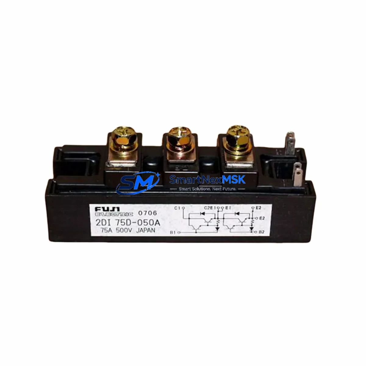
The FUJI 2DI75D-050A is a dual IGBT power module rated at 75A / 500V, engineered for seamless integration into legacy and active 2DI-D Series drive and inverter platforms. As industrial facilities accelerate the retirement of aging power conversion equipment, the 2DI75D-050A has become a critical retrofit component for engineers tasked with upgrading control cabinets, replacing discontinued modules, and restoring production continuity without full system overhauls.
Whether you are replacing a failed module in a FUJI FRENIC or G11 series inverter, upgrading a legacy drive cabinet, or migrating from an older IGBT generation, the 2DI75D-050A provides a verified drop-in solution that preserves existing wiring topology, gate drive compatibility, and thermal interface requirements. Its dual-switch configuration simplifies half-bridge replacement in single-phase and three-phase converter stages, reducing retrofit labor time and minimizing exposure to unplanned downtime.
Upgrade Compatibility Table
| Parameter | 2DI75D-050A | Notes |
|---|---|---|
| Collector Current (Ic) | 75A | Matches legacy 2DI-D Series rating |
| Collector-Emitter Voltage (Vce) | 500V | Compatible with 380V AC input drives |
| Module Configuration | Dual (2-in-1) | Half-bridge topology, direct swap |
| Package / Footprint | Standard FUJI D-Series package | Bolt-down, same mounting hole pattern |
| Gate Drive Voltage | ±15V recommended | Compatible with existing gate driver boards |
| Thermal Interface | Flat base, requires thermal grease | Heatsink re-use supported |
| Communication Compatibility | N/A (power stage) | No protocol change required |
| Replacement Recommendation | Direct drop-in for 2DI75D-050 variants | Verify gate resistor values before power-on |
| Commissioning Focus | Gate signal integrity, Vce(sat) check | Use oscilloscope during first power-up |
| Warranty | 12 Months | Covers manufacturing defects |
Retrofit Planning for Existing Automation Systems
Successful integration of the 2DI75D-050A into an existing automation system requires a structured pre-installation review. Begin by auditing the DC bus voltage and confirming that the power supply module feeding the inverter stage delivers stable voltage within the module’s Vce rating. In many retrofit scenarios involving FUJI FRENIC-Multi or FRENIC-Eco drives, the existing 24V control power supply and the gate driver board remain serviceable and do not require replacement alongside the IGBT module.
Terminal block wiring should be mapped against the original schematic before disconnection. The 2DI75D-050A uses the same emitter, collector, and gate terminal layout as predecessor modules in the 2DI-D family, which eliminates the need for wiring harness modifications in most installations. However, engineers should inspect the gate resistor network on the driver PCB — particularly if the original module was a different current class — and adjust gate resistance values if switching speed or EMI characteristics need to be tuned for the new module.
For systems that include a FUJI PXR or PXG temperature controller, a FUJI alpha5 servo drive, or a FUJI FRENIC-HVAC inverter sharing the same control cabinet, the retrofit scope may extend beyond the IGBT module itself. In these cases, the backplane connector integrity, the shared DC bus capacitor bank, and the snubber circuit components should all be inspected and replaced as part of a comprehensive cabinet upgrade. If the system uses a FUJI NP1 or NP8 PLC for sequencing, verify that the PLC I/O module assigned to drive fault monitoring is still correctly mapped after the module swap, as some older program versions use hardcoded fault bit addresses that may require a minor logic revision.
Where the original system relied on a FUJI OPC-G1-SI serial communication card or a PROFIBUS interface module for drive-to-controller communication, no protocol reconfiguration is required following an IGBT module replacement — the communication stack operates independently of the power stage. Confirm that the HMI screen (if present) correctly reflects the drive’s operational status after the swap by running a short jog cycle before returning the line to full production speed.
Downtime Control During System Migration
Minimizing production interruption during an IGBT module replacement requires advance preparation. Before scheduling the maintenance window, confirm that a tested 2DI75D-050A unit is on-site and has passed incoming inspection — including a static gate-emitter resistance check and a visual inspection of the module base for flatness. Pre-stage all tools, thermal interface material, and torque specifications for the mounting hardware.
Back up the drive parameter set using the drive’s built-in parameter copy function or an external keypad memory unit before powering down. This ensures that acceleration ramps, carrier frequency settings, motor nameplate data, and fault history are preserved and can be restored immediately after the module is replaced and the drive is powered back on. For drives integrated with a FUJI FRENIC-Loader PC tool, save the parameter file to a local directory as an additional safeguard.
During the swap, discharge the DC bus capacitors fully before touching any internal components — use a calibrated voltmeter to confirm bus voltage is below 30V. Reinstall the 2DI75D-050A with fresh thermal compound applied evenly across the module base, torque the mounting bolts to specification, and reconnect gate and power terminals in reverse order of removal. After power restoration, monitor the module’s heatsink temperature during the first 15–30 minutes of operation to confirm thermal contact is adequate. A properly installed module will reach thermal equilibrium without triggering an overheat fault.
Retrofit Support FAQ
Q1: Is the 2DI75D-050A a direct replacement for the 2DI75D-050?
Yes. The 2DI75D-050A is the current production revision of the 2DI75D-050 and is electrically and mechanically interchangeable. No wiring or mounting modifications are required for a standard swap.
Q2: What commissioning steps are required after installation?
After installation, perform a static gate-emitter check, restore drive parameters from backup, run a no-load jog test at low frequency, and verify output current balance across all three phases before returning to full load. Monitor heatsink temperature during the first production run.
Q3: Does the module ship pre-tested?
Yes. Each 2DI75D-050A unit undergoes outgoing electrical testing prior to shipment, including Vce(sat), gate threshold voltage, and leakage current verification. A test report is available upon request.
Q4: What does the 12-month warranty cover?
The 12-month warranty covers manufacturing defects in materials and workmanship from the date of shipment. It does not cover damage resulting from incorrect installation, overvoltage events, or operation outside the module’s rated parameters. Warranty claims are processed with return of the defective unit for inspection.
© 2026 SMARTNEXMSK. All rights reserved.
Original Source: https://smartnexmsk.com
Contact: sales@smartnexmsk.com | +86 18259474341