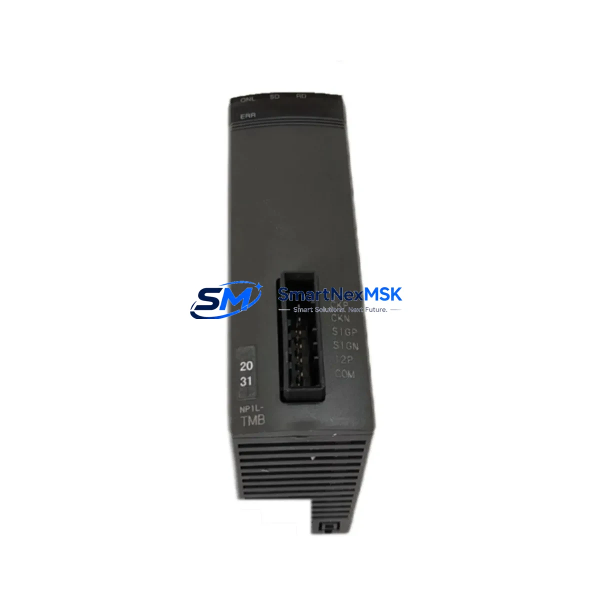
FUJI 2MBI300N-060 Maintenance-Ready Spare for N-Series Automation
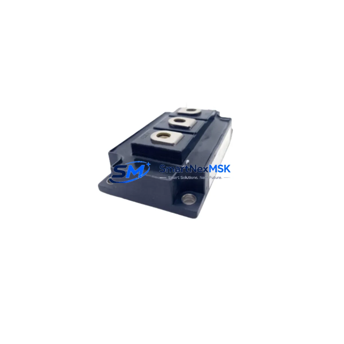
The FUJI 2MBI300N-060 is an original dual-pack IGBT power module rated at 300A / 600V, engineered for high-current switching applications in industrial variable frequency drives (VFDs), servo inverters, and regenerative power converters. As a core switching element in FUJI N-Series drive systems, this module is a critical spare for maintenance engineers managing uptime in continuous-process manufacturing, CNC machining centers, crane hoisting systems, and heavy-duty conveyor lines. Sourced directly from authorized supply channels, each unit is pre-shipment tested and backed by a 12-month warranty — ensuring your replacement program meets both quality and traceability requirements.
When a 2MBI300N-060 fails in service, the resulting unplanned downtime can cascade across an entire production line. Proactive spare parts stocking of this module — alongside its associated gate driver boards, DC bus capacitors, and thermal interface components — is the single most effective strategy for reducing mean time to repair (MTTR) in IGBT-based drive cabinets. This product page is designed to support both maintenance planners building BOM-level spare kits and procurement engineers sourcing verified replacements for aging FUJI N-Series installations.
Spare Maintenance Table
| Parameter | Specification |
|---|---|
| Part Number / SKU | 2MBI300N-060 |
| Manufacturer | FUJI Electric |
| Module Type | Dual-Pack IGBT Power Module |
| Collector Current (Ic) | 300A |
| Collector-Emitter Voltage (Vces) | 600V |
| Series Compatibility | FUJI N-Series VFDs & Inverters |
| Package / Footprint | Standard FUJI 7th-Gen Module Package |
| Gate Drive Voltage (Vge) | ±15V (recommended) |
| Operating Temperature | -40°C to +150°C (Tj) |
| Mounting | Screw-mount to heatsink with thermal compound |
| Application Environment | Industrial drives, servo inverters, UPS, regenerative converters |
| Origin | Japan |
| Condition | Original New (OEM) |
| Warranty | 12 Months |
| Pre-shipment Testing | Vce(sat), leakage current, gate threshold verified |
Maintenance Planning for Continuous Operation
Replacing a 2MBI300N-060 in a live drive cabinet is rarely an isolated task. Experienced maintenance engineers treat an IGBT module failure as a trigger for a broader inspection of the surrounding power circuit. Before returning the drive to service, the following components should be inspected or replaced as part of a structured corrective maintenance routine.
Gate Driver Board: The gate driver PCB that interfaces directly with the 2MBI300N-060 should be checked for burnt resistors, failed optocouplers, and degraded bootstrap capacitors. FUJI N-Series drives typically use a dedicated gate driver card matched to the module’s switching characteristics — a failed module often indicates overstress on the driver as well. In many N-Series frames, the gate driver board carries the designation EP-3955B or similar; confirm the exact part number from the drive’s service manual before ordering a replacement.
DC Bus Capacitors: Electrolytic DC link capacitors in the same inverter section should be measured for capacitance and ESR. Capacitor degradation is a leading cause of IGBT overvoltage stress. Replacing the 2MBI300N-060 without addressing capacitor health risks repeat failure within months. For N-Series drives in the 75–160kW range, DC bus capacitor banks are typically rated 2200–4700µF / 450V and should be replaced as a matched set.
Snubber and Clamp Circuits: Inspect snubber capacitors and transient voltage suppression (TVS) components mounted near the module. These protect the IGBT from voltage spikes during switching and are often overlooked during module replacement. A degraded snubber capacitor — even one that measures within tolerance at DC — may fail to suppress fast-rising voltage transients under load.
Current Sensors and Hall-Effect Transducers: The current feedback loop feeding the drive’s control board depends on accurate current sensing. A shorted IGBT can damage current transducers in the same phase leg — verify output linearity before recommissioning. FUJI N-Series drives commonly use LEM-type Hall-effect sensors; check the sensor’s ±15V supply rail and zero-offset output before clearing the fault.
Control Power Supply Module (SMPS): The 24VDC or 15VDC switch-mode power supply feeding the gate driver and control logic should be load-tested. Voltage ripple or dropout under load can cause erratic gate signals and premature IGBT failure. If the SMPS output shows more than 200mV ripple under full gate driver load, replace it before reinstalling the 2MBI300N-060.
I/O Terminal Blocks and Signal Wiring: Inspect the drive’s I/O terminal strip for loose connections, corroded contacts, and insulation breakdown. Vibration-induced terminal loosening is common in high-current drive cabinets and can cause nuisance trips that mask underlying hardware faults. Phoenix Contact or Weidmüller-style terminal blocks used in FUJI N-Series panels should be re-torqued to specification during any corrective maintenance event.
Thermistor and Temperature Sensor: The NTC thermistor or PT100 sensor mounted on the heatsink adjacent to the 2MBI300N-060 should be resistance-checked at ambient temperature. A failed temperature sensor can prevent the drive’s thermal protection from activating, leading to repeat module burnout. Replace the thermistor if resistance deviates more than 5% from the nominal curve.
Semiconductor Fuses: Fast-acting semiconductor fuses protecting the IGBT module should be replaced as a matter of course following any module failure. Do not reuse fuses that have experienced a fault current event — internal element degradation may not be visible externally. Bussmann or Ferraz Shawmut gR-type fuses rated for the module’s peak current are the standard choice for N-Series drive protection.
Communication and Fieldbus Modules: If the drive is integrated into a PROFIBUS-DP, DeviceNet, or Modbus RTU network, verify that the communication option card and its wiring harness are intact after the fault event. A drive fault can corrupt fieldbus node addressing in some configurations; re-initialize the node address and verify cyclic data exchange before returning to automatic mode.
Heatsink and Thermal Interface: Clean the heatsink contact surface with isopropyl alcohol and apply fresh thermal compound before installing the replacement 2MBI300N-060. Degraded thermal interface material is a primary contributor to elevated junction temperatures and shortened module life. Use a silicone-free, high-conductivity compound rated for industrial power electronics applications.
Site Replacement Workflow
The 2MBI300N-060 is a direct form-fit-function replacement for earlier FUJI N-Series IGBT modules sharing the same package footprint and electrical ratings. The following workflow minimizes downtime and ensures system compatibility during site replacement.
Step 1 — Isolation and Lockout/Tagout: De-energize the drive, discharge the DC bus to below 50V (verify with a calibrated meter), and apply LOTO before opening the cabinet. Confirm bus voltage with a CAT III-rated multimeter.
Step 2 — Module Removal: Disconnect gate driver connectors and power terminals. Remove mounting screws and extract the failed module. Photograph all terminal connections before disassembly to ensure correct reassembly.
Step 3 — Heatsink Preparation: Clean the heatsink surface with isopropyl alcohol. Apply a uniform, thin layer of thermal compound. Inspect for heatsink warping, corrosion, or blocked cooling fins.
Step 4 — Module Installation: Mount the 2MBI300N-060 to the heatsink and torque screws to the manufacturer’s specification (typically 3–5 Nm). Reconnect power terminals and gate driver connectors per the original wiring diagram. Verify correct phase assignment (U/V/W) before closing the cabinet.
Step 5 — Pre-Power Verification: Measure collector-emitter resistance in both directions with a multimeter. Verify gate-emitter resistance is within the expected range (typically 10–100Ω depending on gate resistor). Confirm no short circuits before energizing.
Step 6 — Commissioning: Power up the drive in a no-load condition. Monitor output current waveform symmetry across all three phases using a clamp meter or oscilloscope. Verify thermal performance under partial load before returning to full production. Log the replacement in the site maintenance record with the module serial number and installation date.
This workflow applies equally to legacy FUJI N-Series installations where the original module may have been in service for 10–15 years. The 2MBI300N-060 is fully compatible with these older drive frames, making it an ideal solution for extending the operational life of installed equipment without requiring a full drive replacement — a significant capital cost saving for facilities managing aging automation infrastructure.
Spare Parts Support FAQ
Q1: Is the 2MBI300N-060 a direct drop-in replacement for older FUJI N-Series IGBT modules?
Yes. The 2MBI300N-060 uses the standard FUJI 7th-generation module package and is electrically and mechanically compatible with N-Series drive frames that originally specified this part number. No firmware or parameter changes are required in the drive controller when replacing a like-for-like module. For cross-series compatibility (e.g., substituting into an older E-Series or G-Series frame), consult the drive’s service manual to confirm package dimensions and gate drive requirements.
Q2: How is each unit tested before shipment?
Every 2MBI300N-060 unit undergoes pre-shipment electrical verification including Vce(sat) measurement, gate threshold voltage check, and collector-emitter leakage current test. Units that fail any parameter are quarantined and not dispatched. A test record is available upon request for quality-critical or ISO 9001-audited maintenance programs.
Q3: What is the recommended spare parts stocking strategy for this module?
For facilities operating more than two FUJI N-Series drives using the 2MBI300N-060, a minimum stock of one spare module per drive frame is recommended. For continuous-process plants where unplanned downtime carries high production cost, a buffer of two to three units per site is advisable. Modules should be stored in anti-static packaging at 15–35°C with relative humidity below 75% RH, away from magnetic fields and mechanical vibration.
Q4: What does the 12-month warranty cover, and how are claims processed?
The 12-month warranty covers manufacturing defects, parameter non-conformance, and premature failure under normal operating conditions. It does not cover damage resulting from incorrect installation, overvoltage events beyond rated Vces, or operation without adequate thermal management. Warranty claims are processed with return of the defective unit and a brief fault description. Replacement units are dispatched within 5 business days of claim approval, supporting your site’s minimum downtime objectives.
© 2026 SMARTNEXMSK. All rights reserved.
Original Source: https://smartnexmsk.com
Contact: sales@smartnexmsk.com | +86 18259474341