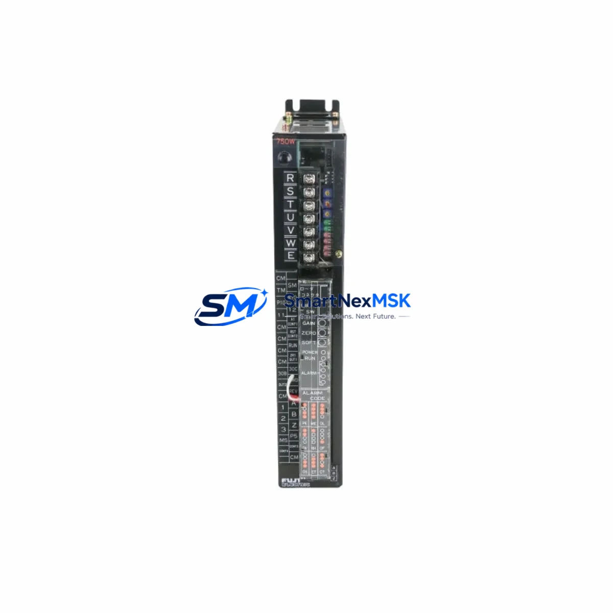
FUJI ELECTRIC 7500S-AZ Retrofit-Ready Servo Driver for 7500S Control Systems
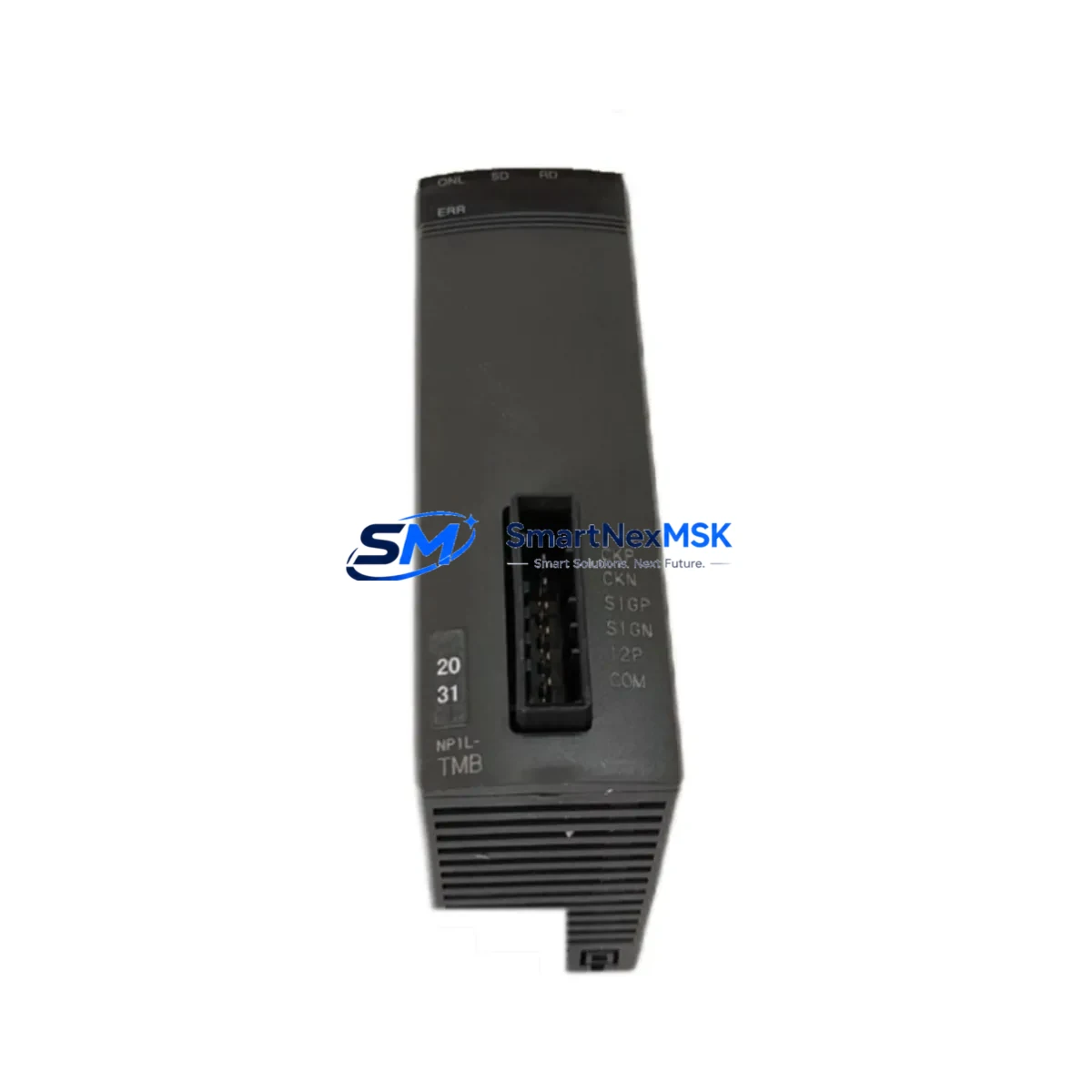
The FUJI ELECTRIC 7500S-AZ (SKU: 7500S-AZ-90130042A-80399-110M-PS) is a retrofit-ready servo driver engineered for seamless integration into existing 7500S Series control architectures. Whether you are replacing a discontinued unit on an aging production line, upgrading a legacy control cabinet, or migrating from an obsolete drive platform, this module delivers the compatibility, reliability, and verified performance that industrial automation engineers demand. Sourced from authorized supply channels and subjected to pre-shipment functional testing, every unit ships with a 12-month warranty and full traceability documentation.
Upgrade Compatibility Table
| Parameter | Details |
|---|---|
| SKU / Part Number | 7500S-AZ-90130042A-80399-110M-PS |
| Series Compatibility | FUJI ELECTRIC 7500S Series |
| Direct Replacement For | FUJI ELECTRIC 7500S-AZ (discontinued / end-of-life variants) |
| Drive Type | AC Servo Driver |
| Mounting / Installation | DIN rail or panel mount; matches original 7500S footprint |
| Communication Protocol | Compatible with existing 7500S Series fieldbus and serial links |
| I/O Interface | Terminal block wiring compatible; no re-termination required in standard retrofit |
| Backplane / Rack Interface | Fits standard 7500S Series rack; module address configurable via DIP switch or parameter |
| Program Compatibility | Existing ladder logic and motion programs remain valid; parameter re-entry may be required |
| HMI Screen Compatibility | Existing HMI tag mapping retained; verify drive status word bit assignments |
| Pre-Shipment Testing | Full functional test performed before dispatch |
| Warranty | 12 Months from date of shipment |
| Country of Origin | Japan |
Retrofit Planning for Existing Automation Systems
Successful retrofit of the FUJI ELECTRIC 7500S-AZ begins well before the replacement unit arrives on site. Engineers should start by auditing the existing control cabinet layout: confirm the power supply capacity — typically the FUJI ELECTRIC PSR series power supply module or equivalent 24 VDC rail supply — can sustain the inrush and steady-state current draw of the replacement drive without tripping upstream breakers or causing voltage sag on shared rails.
Next, document all terminal wiring on the outgoing unit. The 7500S-AZ uses a standard screw-terminal I/O block; photograph or sketch the wiring before disconnection. In most 7500S Series cabinets, the FUJI ELECTRIC CNC I/O expansion module or a dedicated 7500S digital I/O module handles auxiliary signals — confirm that these remain powered and addressed correctly during the swap to avoid nuisance faults on the PLC side.
Backplane and rack integrity is critical. The 7500S-AZ seats into the FUJI ELECTRIC 7500S Series base unit rack; inspect the backplane connector for bent pins or oxidation before inserting the replacement. Module address assignment — whether via rotary switch, DIP switch, or software parameter — must match the address map stored in the host controller, typically a FUJI ELECTRIC MICREX-SX Series PLC or compatible FUJI ELECTRIC FRENIC Series inverter controller, to ensure the CPU recognizes the new drive without a configuration mismatch alarm.
Communication link verification is the next checkpoint. If the existing system uses FUJI ELECTRIC T-Link or a Modbus RTU chain, confirm that the baud rate, parity, and station number parameters are re-entered identically on the replacement 7500S-AZ. Where the system integrates a FUJI ELECTRIC V9 Series HMI or equivalent operator panel, verify that the drive status word, fault code register, and speed reference tag addresses remain consistent — a mismatch here will cause the HMI to display incorrect run/fault states even when the drive is operating normally.
For systems that include a FUJI ELECTRIC programming cable (USB-RS485 adapter) or dedicated loader software, retain the original parameter file backup before powering down the old unit. Re-upload the parameter set to the replacement 7500S-AZ during commissioning and perform a no-load test run before reconnecting the mechanical load. Where the retrofit involves simultaneous replacement of the FUJI ELECTRIC encoder feedback module or resolver interface card, ensure the new encoder cable shielding is grounded at the drive end only to prevent ground loop interference.
Downtime Control During System Migration
Minimizing unplanned downtime is the primary concern for any 7500S-AZ replacement project. The recommended approach is a staged hot-swap preparation: pre-configure the replacement drive offline using the parameter backup from the outgoing unit, verify all DIP switch and rotary address settings match the original, and stage the unit in the cabinet with wiring pre-terminated but not yet energized. This reduces the live changeover window to the time required for a controlled shutdown, physical swap, and power-on verification — typically 30 to 90 minutes for a single-axis retrofit.
To protect existing program logic, never clear the host PLC memory during the drive swap. The FUJI ELECTRIC MICREX-SX or equivalent controller retains its ladder program and I/O table in non-volatile memory; a controlled CPU stop followed by a warm restart after the drive replacement preserves all program data. If the system uses a FUJI ELECTRIC motion controller module for coordinated multi-axis control, place the affected axis in a safe inhibit state before disconnection and restore it last during recommissioning to prevent axis synchronization faults.
Field continuity is maintained by keeping all other axes and I/O modules powered throughout the swap where the electrical design permits. Communicate the planned outage window to the production scheduler in advance, and have a qualified commissioning engineer on site for the first powered test run. All units supplied by SMARTNEXMSK are pre-tested and documented, reducing the risk of a second outage caused by a defective replacement part.
Retrofit Support FAQ
Q1: Is the 7500S-AZ-90130042A-80399-110M-PS a direct drop-in replacement for the original FUJI ELECTRIC 7500S-AZ?
A: Yes. The unit matches the original 7500S-AZ in form factor, terminal layout, and communication interface. Parameter re-entry from your existing backup file is required; no hardware modification to the cabinet is necessary in a standard retrofit scenario.
Q2: What wiring checks should I perform before powering on the replacement drive?
A: Verify main power input phasing and voltage level, confirm control terminal wiring matches the original drawing, check that the encoder or resolver cable is correctly seated and shielded, and ensure the module address matches the host controller configuration. A megger test on the motor winding is recommended if the motor has been idle for an extended period.
Q3: How do I confirm communication compatibility with my existing PLC or HMI?
A: Re-enter the original baud rate, parity, stop bits, and station address parameters on the replacement 7500S-AZ. Perform a loopback communication test from the host controller before enabling the drive output. For HMI integration, verify that the drive register map matches the tag addresses configured in your HMI project file.
Q4: What does the 12-month warranty cover, and what is the claims process?
A: The 12-month warranty covers manufacturing defects and functional failures under normal operating conditions from the date of shipment. In the event of a warranty claim, contact SMARTNEXMSK with the order reference, a description of the fault, and the pre-shipment test report supplied with the unit. Replacement or repair will be arranged promptly to minimize your production impact.
© 2026 SMARTNEXMSK. All rights reserved.
Original Source: https://smartnexmsk.com
Contact: sales@smartnexmsk.com | +86 18259474341