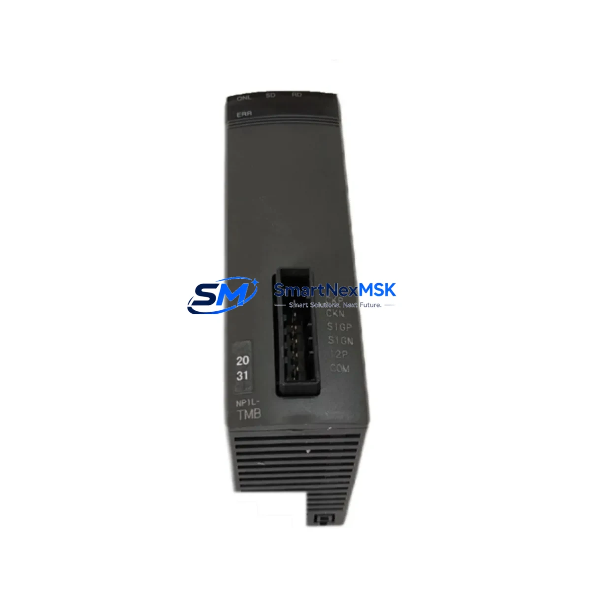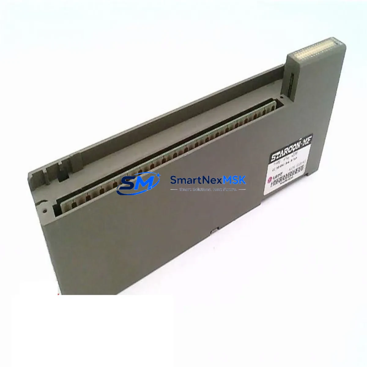
FUJI Electric FTU123B Retrofit-Ready Digital Input Module for MICREX-SX Control Systems
The FUJI Electric FTU123B is a retrofit-ready digital input (DI) module engineered for seamless integration into MICREX-SX series programmable logic controller platforms. As legacy MICREX-SX installations reach end-of-life or face discontinued spare-parts availability, the FTU123B provides a verified drop-in replacement path that preserves existing rack architecture, terminal wiring, and ladder logic programs — minimizing engineering rework and unplanned downtime during system modernization projects.
Whether you are managing a planned control cabinet upgrade, responding to an emergency module failure, or executing a phased I/O expansion across a multi-rack MICREX-SX backplane, the FTU123B delivers the channel density, signal compatibility, and diagnostic transparency required by industrial maintenance teams operating in process, discrete, and hybrid manufacturing environments.
Upgrade Compatibility Table
| Parameter | FTU123B Specification | Retrofit Notes |
|---|---|---|
| Module Type | Digital Input (DI) | Direct replacement for equivalent MICREX-SX DI modules |
| Series Compatibility | MICREX-SX Series | Verify backplane slot assignment and rack address before installation |
| Rack / Backplane Interface | MICREX-SX standard backplane connector | Confirm backplane revision; older NP1B-series racks may require adapter verification |
| Terminal Wiring | Screw-terminal block, field-side wiring retained | Re-use existing field wiring; verify terminal torque spec per FUJI wiring manual |
| Module Address / Slot Config | Configured via CPU parameter or rotary switch (model-dependent) | Match original module address in SPB or SX-Programmer before hot-swap |
| Communication Protocol | Internal MICREX-SX backplane bus | No external protocol change required; compatible with existing NP1L-RS4 or T-Link links |
| Program Compatibility | Full ladder/FBD logic retained | No program modification required if I/O address mapping is preserved |
| HMI Screen Impact | None (tag-based addressing unchanged) | Verify HMI tag references in MONITOUCH or equivalent operator panel |
| Power Supply Requirement | Supplied via backplane (no external 24 VDC required for module logic) | Confirm NP1PS power supply capacity covers total rack load after module addition |
| Installation Format | Rack-mount, standard MICREX-SX slot | No panel cutout modification required |
| Warranty | 12-Month Warranty | Covers manufacturing defects; includes pre-shipment functional test report |
Retrofit Planning for Existing Automation Systems
A successful FTU123B retrofit begins well before the module arrives on-site. Engineering teams should start by auditing the existing MICREX-SX rack configuration, documenting every occupied slot, the installed NP1B-series base unit revision, and the current NP1PS power supply load budget. When adding or replacing DI modules, the total current draw across all installed I/O — including any NP1L-RS4 serial communication modules, NP1L-ET1 Ethernet interface modules, and analog I/O cards — must remain within the power supply’s rated output. Overlooking this step is one of the most common causes of intermittent faults after a module swap.
Terminal wiring documentation is equally critical. Before removing the legacy DI module, photograph or transcribe the field-side wiring layout. The FTU123B uses a compatible screw-terminal arrangement, but wire labeling should be verified against the original electrical drawings to prevent mis-termination of proximity sensor commons, dry-contact inputs, or encoder feedback signals. If the original installation used a FUJI terminal block adapter or relay output intermediate terminal board, confirm that the adapter pinout matches the FTU123B connector footprint.
For sites running SX-Programmer Expert or the legacy SPB programming software, the module address and I/O assignment table should be exported and archived before any hardware change. The FTU123B slot address is typically set via the CPU’s I/O parameter configuration or a physical rotary switch on the module face. Mismatched addresses will cause the CPU — whether an NP1PS-08 or NP1PS-24 class controller — to flag an I/O configuration error on startup, preventing normal scan cycle execution.
Sites that have integrated MONITOUCH HMI panels or third-party SCADA systems via Modbus RTU or FUJI T-Link protocol should verify that all DI channel tag references remain valid after the swap. Because the FTU123B preserves the original I/O address space, no HMI screen rebuild is typically required — but a forced I/O test from the programming terminal is recommended to confirm all 16 (or 32, depending on variant) input channels respond correctly before returning the line to production.
For multi-rack installations using NP1B expansion racks connected via the MICREX-SX inter-rack cable, confirm that the expansion rack’s slot numbering offset is correctly reflected in the CPU parameter file. Adding the FTU123B to an expansion rack without updating the parameter table will result in address conflicts with other installed modules such as NP1W analog input modules or NP1L-RS2 RS-232C communication modules.
Downtime Control During System Migration
Minimizing production downtime during a MICREX-SX module replacement requires a structured pre-outage preparation protocol. Begin by scheduling the swap during a planned maintenance window and preparing a rollback kit — the original module (if still functional), a backup copy of the CPU program on a FUJI memory cassette or SD card, and a printed I/O wiring diagram.
Before powering down the rack, place the CPU in STOP mode and force all outputs to a safe state. Document the current status of all DI channel indicators on the legacy module. After installing the FTU123B, power the rack back up and observe the module’s RUN and ERR LEDs. A solid RUN LED with no ERR indication confirms successful backplane recognition. Proceed to an online I/O forced test from SX-Programmer to verify each input channel individually before releasing the CPU to RUN mode.
For critical continuous-process applications where even a brief stop is unacceptable, consider a parallel wiring strategy: install the FTU123B in an adjacent available slot, mirror the field wiring to both modules temporarily, and validate the new module’s channel responses against the live production signals before cutting over. This approach keeps the original program logic active on the legacy module while the replacement is verified — effectively reducing the cutover window to under five minutes.
All pre-shipment FTU123B units from SMARTNEXMSK undergo a functional burn-in test and are shipped with a test report. The 12-month warranty covers manufacturing defects identified during commissioning or normal operation, providing additional assurance for maintenance teams operating under tight budget and reliability constraints.
Retrofit Support FAQ
Q1: Is the FTU123B a direct drop-in replacement for my existing MICREX-SX digital input module?
In most MICREX-SX rack configurations, yes. The FTU123B is designed to occupy the same backplane slot, use the same terminal wiring layout, and retain the same I/O address mapping as the original module. However, you should verify the exact variant suffix of your legacy module against the FTU123B datasheet to confirm channel count, input voltage range (typically 24 VDC sink/source), and filter time settings match your application requirements.
Q2: Do I need to modify my ladder logic or SX-Programmer project after installing the FTU123B?
No program modification is required if the module is installed in the same slot with the same address configuration as the original. The FTU123B preserves the I/O address space recognized by the MICREX-SX CPU. Simply confirm the module address via the rotary switch or CPU parameter file, perform a forced I/O test, and return the CPU to RUN mode.
Q3: What commissioning steps are recommended after installation?
After seating the FTU123B in the rack and powering up, check the RUN/ERR LED status, then use SX-Programmer’s online monitor to verify all DI channels are reading correctly. Perform a forced input test on each channel using a test signal source or by actuating the connected field devices. Confirm that the MONITOUCH HMI (or equivalent) displays the correct status for each input before releasing to production.
Q4: What does the 12-month warranty cover, and what is the return process?
The 12-month warranty covers manufacturing defects in materials and workmanship from the date of shipment. Each unit ships with a pre-shipment functional test report. If a defect is identified during the warranty period, contact SMARTNEXMSK at sales@smartnexmsk.com with your order number and a description of the fault. Replacement or repair will be arranged with priority handling to minimize your system downtime.
© 2026 SMARTNEXMSK. All rights reserved.
Original Source: https://smartnexmsk.com
Contact: sales@smartnexmsk.com | +86 18259474341