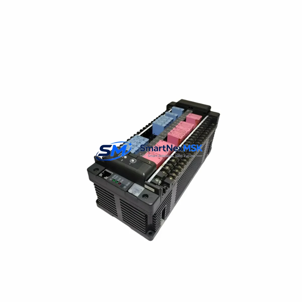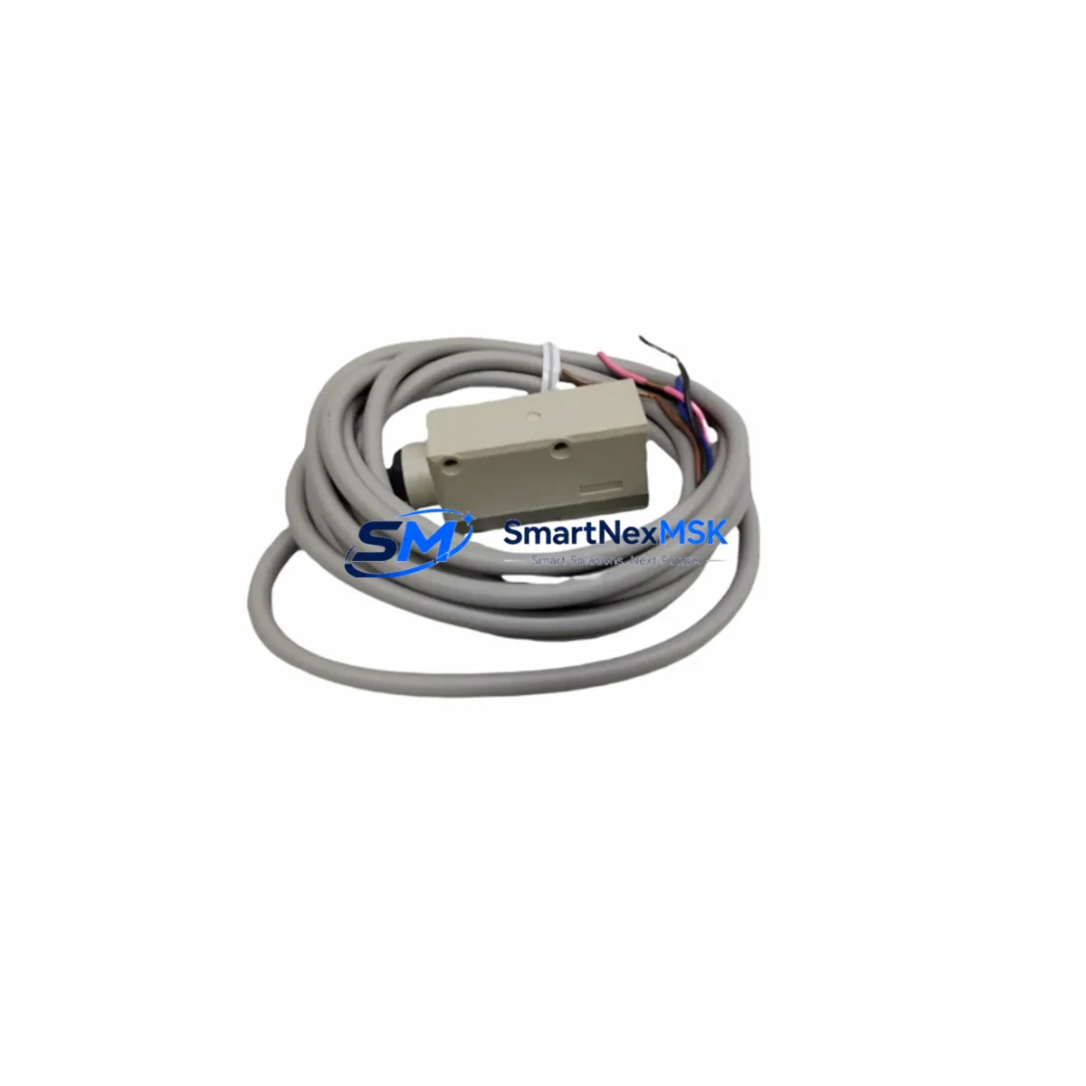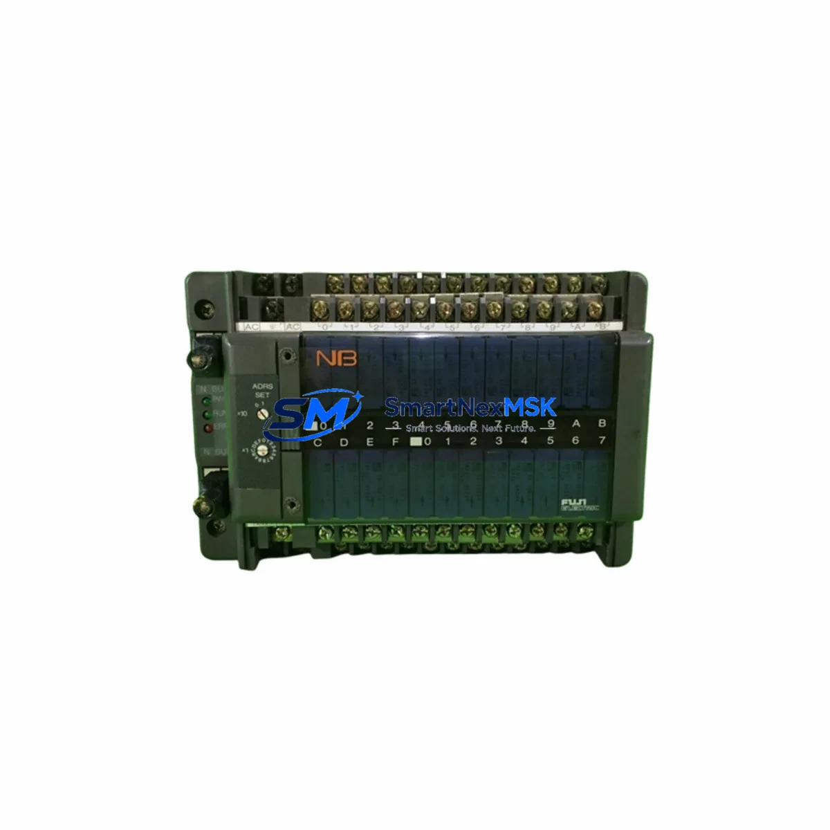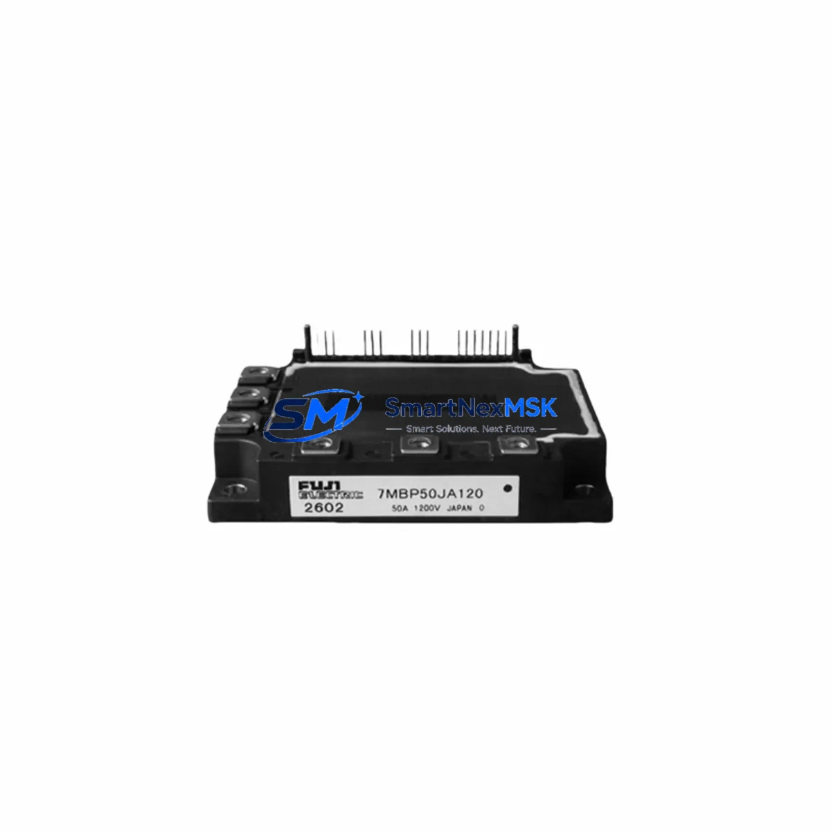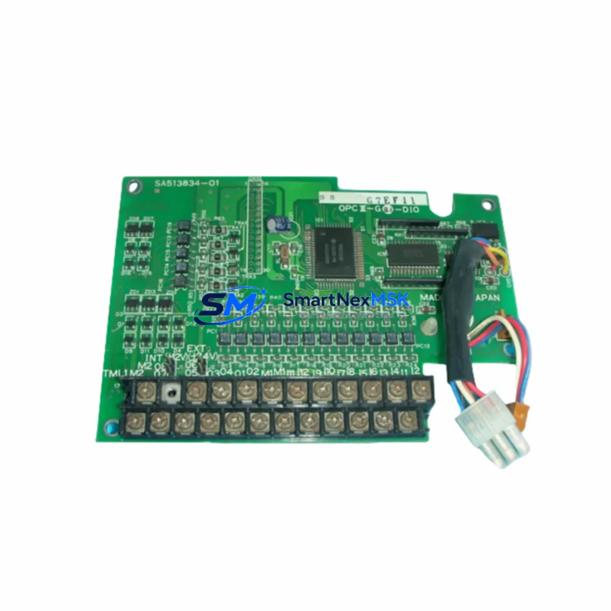
FUJI Electric SA513834-01 Maintenance-Ready Spare for MICREX-SX Automation
The FUJI Electric SA513834-01 is a critical control module within the MICREX-SX programmable logic controller platform — one of FUJI Electric’s most widely deployed automation architectures in process control, discrete manufacturing, and utility infrastructure. For maintenance engineers managing aging MICREX-SX installations, securing a verified, original-specification SA513834-01 spare is not a procurement formality — it is a direct risk-mitigation measure against unplanned downtime and extended outage windows.
This module is sourced as an original spare, inspected prior to dispatch, and shipped with a 12-month warranty covering manufacturing defects and functional integrity. Each unit undergoes pre-shipment functional verification to confirm it meets the electrical and communication specifications required for drop-in replacement in live MICREX-SX control cabinets. Whether you are building a preventive maintenance buffer stock, responding to an emergency fault, or executing a planned overhaul, the SA513834-01 is available from stock with fast global shipping.
Industrial buyers and MRO procurement teams will find this listing suitable for direct PO issuance. Lead time, quantity availability, and export documentation can be confirmed via [email protected] prior to order placement.
Spare Maintenance Table
| Parameter | Specification / Detail |
|---|---|
| Part Number / SKU | SA513834-01 |
| Brand | FUJI Electric |
| Series | MICREX-SX |
| Product Type | PLC Control Module — Spare Part |
| Country of Origin | Japan |
| Compatibility | FUJI Electric MICREX-SX PLC platform; verify rack slot and backplane revision before installation |
| Supply Voltage | Per MICREX-SX system specification (confirm with system documentation) |
| Installation Type | Rack-mount, backplane-connected module |
| Application Environment | Industrial control panels, process automation, discrete manufacturing, utility systems |
| Maintenance Recommendation | Replace on fault indication or as part of scheduled 3–5 year module lifecycle refresh |
| Pre-Shipment Testing | Functional verification performed before dispatch |
| Warranty | 12 Months — covers manufacturing defects and functional integrity |
| Availability | In stock — fast global shipping |
| Export Documentation | Available on request (commercial invoice, packing list, COO) |
Maintenance Planning for Continuous Operation
When a MICREX-SX control system requires SA513834-01 replacement, experienced maintenance engineers treat the event as a trigger for a broader cabinet inspection — not an isolated swap. The MICREX-SX architecture distributes control logic across interconnected modules, and a fault in one component frequently indicates stress or degradation in adjacent hardware.
During the replacement procedure, it is standard practice to inspect the MICREX-SX power supply module (such as the NP1PS series) for output voltage stability and ripple, as power irregularities are a leading cause of premature module failure. The CPU module (NP1L or NP1H series) should be checked for firmware version compatibility with the replacement SA513834-01 to avoid initialization errors after reinsertion.
I/O modules in the same rack — including digital input modules (NP1X series) and digital output modules (NP1Y series) — should be visually inspected for terminal corrosion, loose wiring, and indicator LED status. Analog I/O modules handling 4–20 mA or 0–10 V signals warrant signal loop verification using a calibrated process calibrator before returning the system to automatic mode.
Communication modules, particularly MICREX-SX Ethernet or PROFIBUS interface cards, should be checked for link status and error counters in the engineering software. A module replacement that disrupts the backplane communication bus can cascade into network faults if communication modules are not re-initialized correctly.
Terminal blocks and DIN-rail mounted relay modules in the same control cabinet should be inspected for contact wear, especially in high-cycle applications. Signal isolators on analog input channels protect the PLC from field-side ground loops and transient voltages — their calibration and isolation resistance should be verified during any planned maintenance window. Miniature circuit breakers (MCBs) and fuse holders protecting the 24 VDC control circuit should be tested for correct trip characteristics. Finally, the HMI panel (such as FUJI Electric’s V9 or V10 series) connected to the MICREX-SX CPU should be checked for communication timeout alarms that may have been masked during the fault period.
Building a structured spare parts buffer that includes the SA513834-01 alongside one spare power supply module, one CPU module, and a set of I/O modules appropriate to your installed base is the most effective strategy for reducing mean time to repair (MTTR) in MICREX-SX installations.
Site Replacement Workflow
Step 1 — Fault Isolation: Use the MICREX-SX engineering software (SX-Programmer Expert or equivalent) to read the active fault log and confirm the SA513834-01 as the failed module. Document the slot address, rack number, and any associated I/O fault codes before powering down.
Step 2 — Safe Isolation: Follow your site’s lockout/tagout (LOTO) procedure. Isolate the control cabinet supply and verify zero energy state with a calibrated voltage tester before opening the rack.
Step 3 — Module Removal: Release the module locking lever, disconnect any field wiring connectors, and extract the SA513834-01 from the backplane slot. Note the orientation and connector keying to prevent misalignment of the replacement unit.
Step 4 — Replacement Installation: Insert the new SA513834-01 into the same slot, ensuring full backplane connector engagement. Reconnect field wiring connectors and secure the locking lever. Verify that the module’s DIP switch or rotary address settings (if applicable) match the original configuration documented in Step 1.
Step 5 — Power-Up and Verification: Restore control power and observe the module’s status LEDs. Use the engineering software to confirm the module is recognized by the CPU, that no new fault codes are generated, and that all associated I/O channels are reporting correctly. Perform a functional test of the controlled process segment before returning to automatic operation.
Step 6 — Documentation: Record the replacement in the site maintenance log, including the date, replaced part number, new unit serial number, and technician sign-off. Update the spare parts inventory to trigger reorder of a replacement SA513834-01 buffer unit.
This workflow is applicable to both emergency corrective replacements and planned preventive maintenance cycles. The SA513834-01’s direct form-fit-function compatibility with the MICREX-SX platform eliminates the need for software reconfiguration in most standard installations, significantly reducing total downtime from fault detection to system restoration.
Spare Parts Support FAQ
Q1: Is the SA513834-01 a new original part or a refurbished unit?
All SA513834-01 units supplied by SMARTNEXMSK are original spare parts sourced from authorized distribution channels or verified surplus stock. Each unit is inspected and functionally tested before shipment. Refurbished or repaired units are clearly identified as such — if not stated, the unit is original. A 12-month warranty applies to all units covering manufacturing defects and functional performance.
Q2: How do I confirm compatibility with my specific MICREX-SX installation?
Compatibility is determined by the MICREX-SX rack type, backplane revision, and CPU firmware version in your installation. Provide your system’s CPU part number and rack configuration when contacting [email protected], and our technical team will confirm fit before you commit to purchase. We recommend cross-referencing the FUJI Electric MICREX-SX hardware manual for slot assignment rules.
Q3: What is the recommended inventory strategy for SA513834-01 in a multi-system plant?
For plants operating two or more MICREX-SX systems, maintaining a minimum of one SA513834-01 per system type in on-site buffer stock is standard practice. Given the module’s role in control continuity, a 6–12 month replenishment cycle aligned with annual maintenance planning is recommended. SMARTNEXMSK supports blanket order arrangements and scheduled delivery programs for MRO procurement teams managing multi-site inventories.
Q4: What documentation is provided with each shipment?
Each SA513834-01 shipment includes a commercial invoice, packing list, and country of origin declaration (Japan). Pre-shipment test records are available on request. For export-controlled destinations, please confirm regulatory requirements with your import compliance team prior to order placement. All documentation is provided in English; Chinese-language documentation is available on request.
© 2026 SMARTNEXMSK. All rights reserved.
Original Source: https://smartnexmsk.com
Contact: [email protected] | +86 18259474341